Canoeing oar

A technology of paddles and blades, applied in the field of rowing paddles, can solve the problems of sinking of the hull, increase of additional resistance, slow forward speed, etc., and achieve the effects of reducing additional resistance, increasing speed, and improving competition performance.

Inactive Publication Date: 2011-03-30
梅国威
View PDF9 Cites 0 Cited by
  • Summary
  • Abstract
  • Description
  • Claims
  • Application Information

AI Technical Summary

Problems solved by technology

When an athlete strokes water with a straight oar, when the oar just enters the water, the oar shaft and blade are vertical to the water surface. As the athlete paddles hard, according to Newton's third law, the surface of the oar facing the water will be subject to a horizontal force. The forward force, this force is the driving force F, so as to push the boat forward; as the athlete continues to row the oars backward, due to the influence of the straight structure of the oars and the human body structure, the oars will inevitably have a certain inclination, which is different from the water surface. Form a certain angle, that is, the upper end of the paddle shaft is forward, and the lower end of the blade is backward. With the athlete's forceful paddling, according to Newton's third law, the facing surface of the blade will receive a reaction force perpendicular to the facing surface of the blade. The force is the force F mentioned above. According to the mechanical force analysis, the force F can be decomposed into a forward horizontal component force F" parallel to the water surface. This horizontal component force F" is now the real driving force. Forward; a vertical component F perpendicular to the water surface and directed downwards ⊥ , the vertical force component F ⊥ Make the hull sink, according to the knowledge of fluid mechanics, due to the sinking of the hull, the area of ​​the hull contacting the water increases, so that the resistance when the boat advances is greater than the normal resistance f, and this increased resistance is the additional resistance f′ , so that the forward speed of the boat slows down; as the athlete continues to row the paddle backwards, the inclination angle of the paddle increases continuously. According to the force analysis, the additional resistance f′ also increases continuously, which further slows down the forward speed of the boat
[0004] In addition, because the existing blades are in the shape of vertical shovels, the length a of the blades is relatively long, and the hull of the boat is generally shallow, so the point of action of the driving force F that makes the boat move forward and the point of action of the resistance f formed by the water surface are not at the same point. In the plane, as a result of the joint action of these two forces, the hull will generate a moment of forward and backward rotation, so that the hull will sink to a certain extent, and the additional resistance f′ will further increase

Method used


Image

  • Canoeing oar
  • Canoeing oar
  • Canoeing oar

Examples


Embodiment Construction

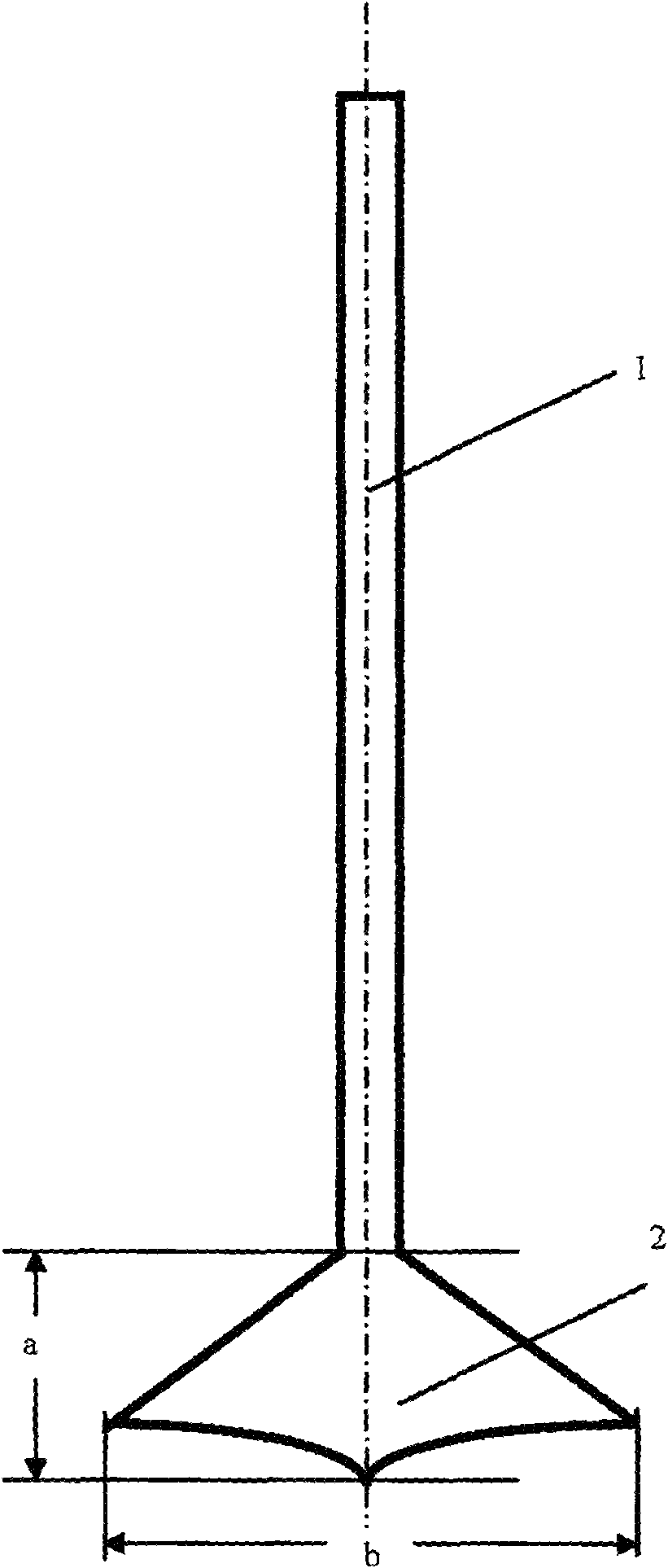
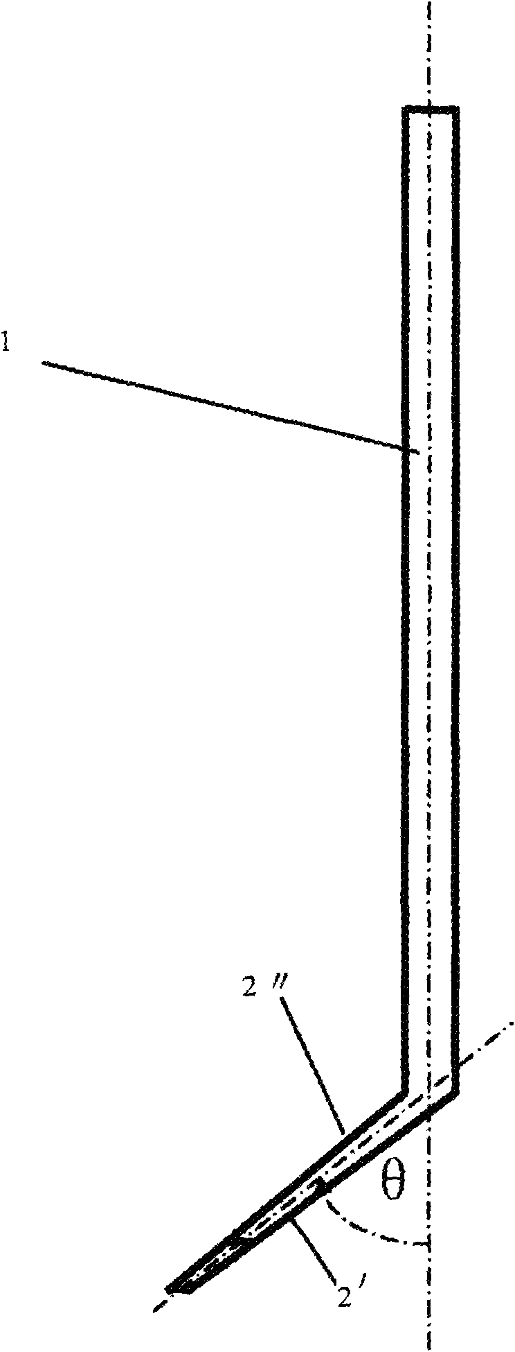
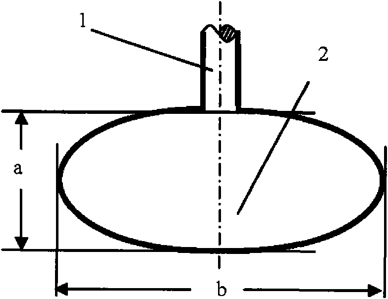
[0019] Figure 1a and Figure 1b Shown is a first embodiment of the rowing paddle of the present invention. in Figure 1a For the front schematic view, the rowing paddle includes two parts, the paddle 1 and the paddle 2, wherein the paddle 2 has a paddle facing water surface 2' and a paddle backwater surface 2 ". The paddle 2 is located at the end of one end of the paddle shaft 1. Wherein The central plane between the upstream surface 2' and the backwater surface 2" of the blade is used as the blade plane where the blade 2 is located, and the central axis of the paddle shaft 1 is used as the paddle shaft axis. The included angle θ between the shaft axis and the plane of the blade is greater than 0° and less than 90°, that is, 0°Figure 1a As mentioned, the paddle 2 can adopt the shape of a bionic duck's foot. Paddle 2 can also be used as figure 2 duck egg shape as described, or as image 3 Wide spade shape shown.

[0020] When the paddle just enters the water, the paddle s...


PUM


Abstract

The invention discloses a canoeing oar which comprise an oar rod and an oar blade, wherein an angle theta is formed between the axis of the oar rod and the plane of the oar blade, and the angle theta is more than 0 degree and less than 90 degrees; the shape of the oar blade meets the conditions that the length is less than or equal to the width; and the oar blade is of a flipper shape, a duck egg shape, or a broad share shape and the like. The canoeing oar of the invention has the advantages that the additional drag f of a canoe moving forward can be reduced, the water-skiing efficiency is enhanced, the forward speed is improved, and the game results of players are improved.

Description

technical field [0001] The invention relates to a rowing paddle. Background technique [0002] At present, the known rowing paddle structure is generally composed of a cylindrical paddle shaft and a vertical shovel-shaped blade (the length of the blade is greater than the width, a>b), and the axis of the paddle shaft is in the plane of the paddle, that is, the paddle The rod and the paddle are in a plane and are a straight structure. [0003] When the boat advances on a calm water surface, it is subject to a horizontal forward thrust F and a horizontal backward resistance f, the horizontal forward thrust F is called the driving force, and the horizontal backward resistance f is called the normal resistance. When an athlete strokes water with a straight oar, when the oar just enters the water, the oar shaft and blade are vertical to the water surface. As the athlete paddles hard, according to Newton's third law, the surface of the oar facing the water will be subject to a...

Claims


Application Information

Patent Timeline
Patent Type & Authority Applications(China)
IPC IPC(8): B63H16/04
Inventor 梅国威
Owner 梅国威
Why Eureka
Try Eureka