
Impeller type fully-automatic washing machine and driving device thereof

A fully automatic washing machine, pulsator technology, applied to washing devices, other washing machines, washing machines with containers, etc., can solve the problems of unsatisfactory vibration damping effect, washing machine vibration, serious and other problems, achieve simple structure and improve washing ratio , the effect of reducing vibration

Active Publication Date: 2011-03-30
HANYU GRP CO LTD
View PDF6 Cites 8 Cited by
  • Summary
  • Abstract
  • Description
  • Claims
  • Application Information

AI Technical Summary

Problems solved by technology

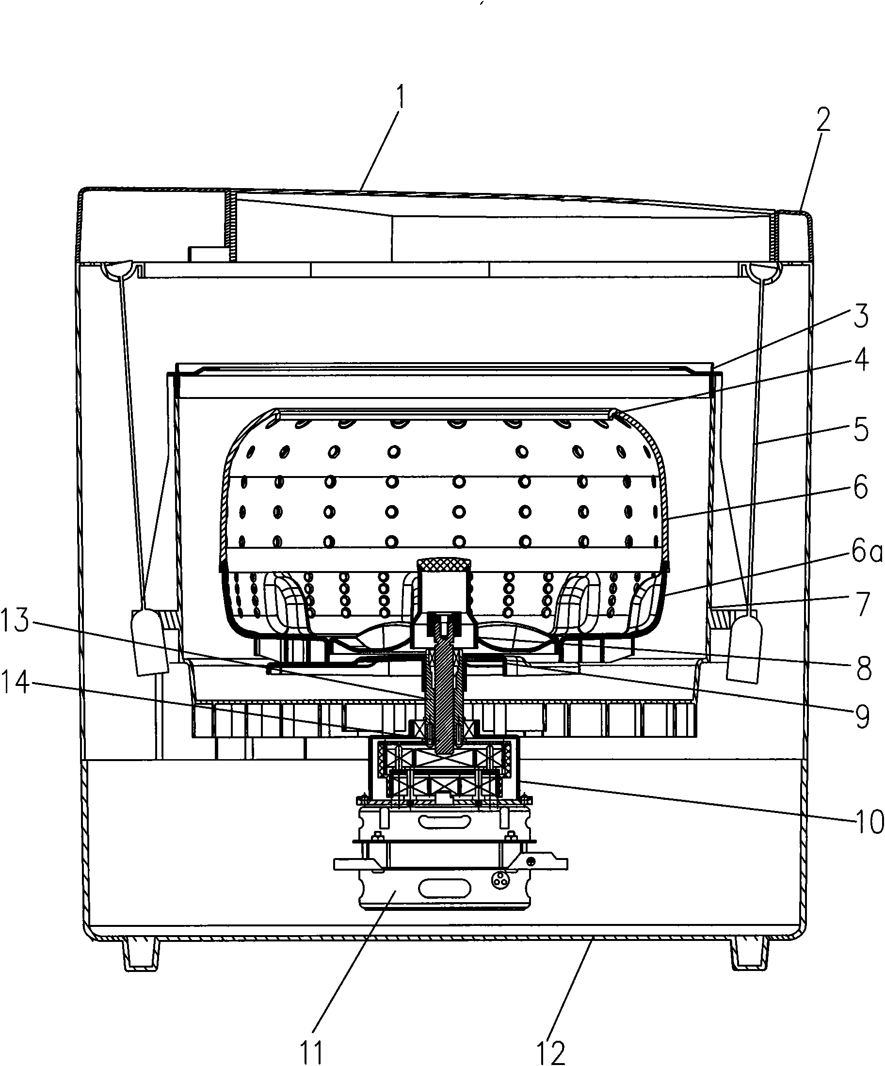
[0008] When the above-mentioned washing machine dehydrates the clothes, the intertwined clothes are often biased against the side wall of the dehydration bucket 6 by the centrifugal force, so that the water tub outside the dehydration bucket of the washing machine vibrates from side to side due to the unbalanced load. In particular, The motor 11 is biased on one side of the water tub 7. When the center of gravity of the entire water tub 7 is not on the central axis, the vibration of the washing machine will be more serious.
[0009] There are two ways to solve the above-mentioned vibration problem in the above-mentioned washing machine: 1. Add a balance block on the other side of the motor to ensure that the center of gravity of the bucket is on the central axis; 2. Use elastic suspenders 5 with different pressures to adjust the four groups The force of the spring is so that the center of gravity of the bucket is adjusted on the central axis, but the vibration damping effect of these methods is not ideal

Method used


Image

  • Impeller type fully-automatic washing machine and driving device thereof
  • Impeller type fully-automatic washing machine and driving device thereof
  • Impeller type fully-automatic washing machine and driving device thereof

Examples


Embodiment 1

[0057] like figure 1 As shown, the washing machine of the present invention includes a base 12, a casing 2 placed on the base 12, a cover 1 that can be opened and closed is arranged on the top of the casing 2, and a water bucket 7 is arranged in the casing 2, and the water bucket 7 is mounted on Rod 5 is suspended on the top of shell 2, and bucket 7 top opening is provided with bung 3, is used for covering bucket 7, prevents the laundry water in bucket 7 from overflowing during washing process. A rotatable perforated dehydration bucket 6 is arranged in the water tub 7, and the clothes to be washed are placed in the perforated dehydration bucket 6.

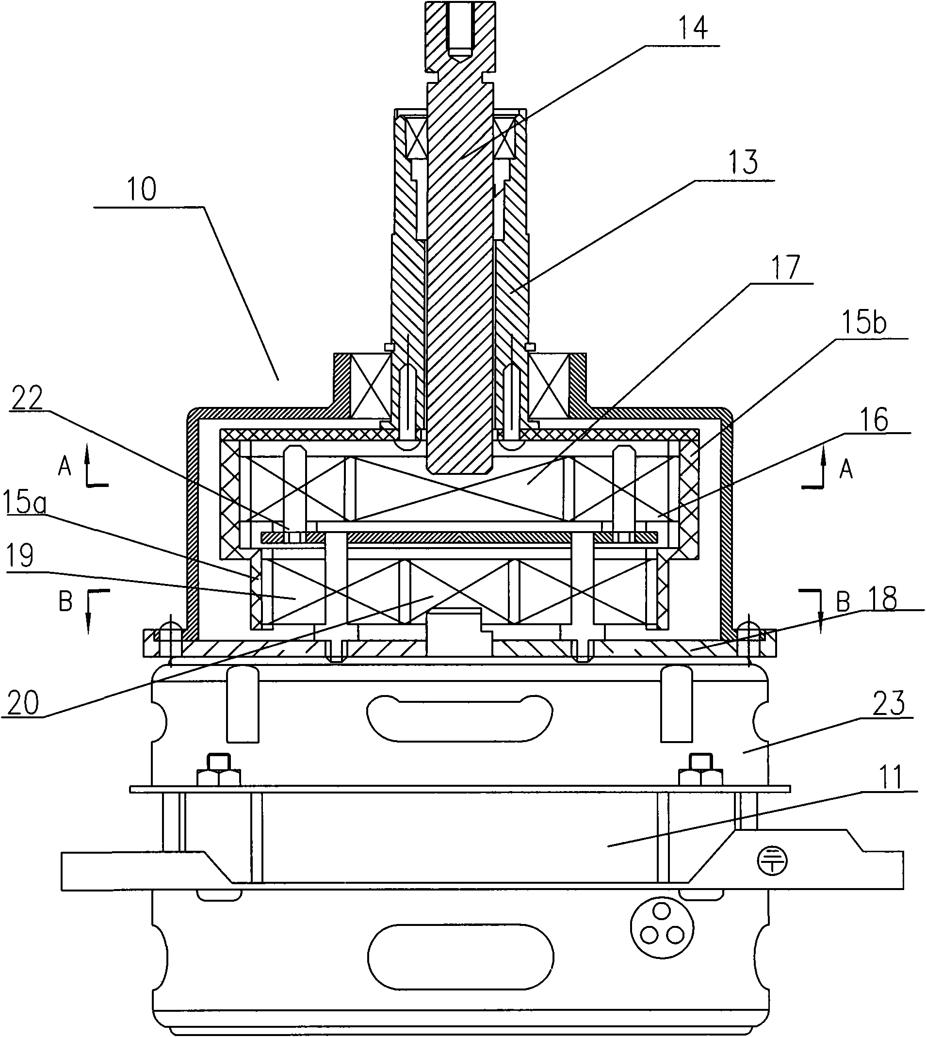
[0058] like figure 1 As shown, the output shaft of the motor 11 is connected with the first central gear 20 of the transmission device 10 installed on its upper part, the transmission device 10 is connected with the dehydration bucket fixed plate 9 through the dehydration bucket shaft 13, and connected with the pulsator 8 throug...

Embodiment 2

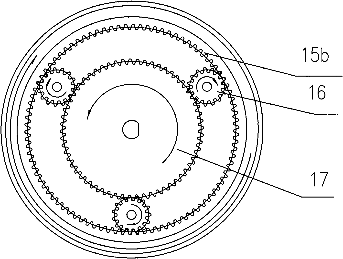
[0078] like image 3 , 4 As shown, the output shaft of the motor 11 is connected with the first sun gear 20 and the second sun gear 17 of the transmission device 10 installed on its upper part. The transmission device 10 is connected to the dehydration bucket fixed plate 9 through the dehydration bucket shaft 13 , and is connected to the pulsator 8 through the pulsator shaft 14 . The dehydration bucket 6 is integrated with the dehydration bucket fixed plate 9, so the dehydration bucket 6 can be driven to rotate when the dehydration bucket shaft 13 rotates. The pulsator shaft 14 is enclosed within the dehydration bucket shaft 13, and its upper end is connected to the pulsator 8 positioned at the center of the bottom of the dehydration bucket 6, so when the pulsator shaft 14 rotates, the pulsator 8 can be driven to rotate, and the dehydration bucket 6 is located inside the water storage bucket 7. Two water outlets are arranged at the bottom of the bucket 7 both sides, and the ...

Embodiment 3

[0091] Refer to as Figure 5 As shown, the washing machine and its transmission device according to Embodiment 3 of the present invention will be described.

[0092] The central position of the bottom of the washing machine tub 7 is equipped with a transmission device 10, and a motor 11 is installed at the bottom center position of the transmission device 10 to directly transmit power to the transmission device 10.

[0093] Image 6 is the main section of the transmission 10, Figure 6a along Image 6 In the cross-sectional view of line A-A in the center, a set of planetary reduction gears is installed in the transmission device 10, including a central gear 17a, an outer planetary gear 15' and 3 or 4 planetary gears 16a, 16b, and the three planetary gears 16a, 16b are arranged on the central gear 17a and the outer planetary gear 15' and meshes with it. One of the planetary gears 16a is connected with the motor shaft 11a, and the other 2 or 3 planetary gears 16b are fixed o...


PUM


Abstract

The invention provides an impeller type fully-automatic washing machine. The impeller type fully-automatic washing machine comprises a chassis (2) and a water-accommodating bucket (7), wherein the water-accommodating bucket (7) is arranged in the chassis (2); a dehydrating bucket (6) is arranged in the water-accommodating bucket (7); an impeller (8) is arranged at the bottom of the dehydrating bucket (6); a driving device (10,11) is arranged below the dehydrating bucket (6); the driving device comprises a motor (11) and a transmission device (10); the transmission device (10) is arranged between the dehydrating bucket (6) and the motor (1), is directly driven by the motor to drive the dehydrating bucket (6) and the impeller (8) to rotate along the opposite direction and comprises one or two groups of planetary reduction gears. The gears are directly driven by the motor to distribute a plurality of groups of power in a speed-reducing mode, wherein the impeller is driven by one group of power to rotate; and the dehydrating bucket is driven by the other one group of power to rotate, so that the washing and dehydrating requirements of the fully-automatic washing machine are met through simple transmission. The impeller type fully-automatic washing machine has a simple structure and high reliability and greatly reduces the manufacturing cost.

Description

technical field [0001] The invention relates to a washing machine and its transmission device, in particular to a pulsator type fully automatic washing machine and its transmission device. Background technique [0002] The pulsator-type automatic washing machine drives the pulsator to rotate through the deceleration of the clutch to generate pulsed water flow. During washing, due to the centrifugal force, the water rises along the inner side of the bucket, and the water in the center of the bucket is strongly sucked downward, forming a strong and powerful downward flow. The rubbing water flow makes the clothes roll up and down freely with the water flow. On the other hand, the contact between the pulsator and the washing liquid increases, which can effectively transfer energy in the washing liquid with low degree of staining. When washing, the laundry motor drives the planetary gear reducer in the clutch through the belt drive. After the reducer is decelerated, the wave whee...

Claims


Application Information

Patent Timeline
Patent Type & Authority Applications(China)
IPC IPC(8): D06F29/02D06F17/06D06F17/08D06F49/00D06F37/40D06F37/24D06F49/04
Inventor 林卫文石华山
Owner HANYU GRP CO LTD
Learn More