Transmission shaft permanent magnet coupling drive and speed regulation device capable of adjusting magnetic torque

A permanent magnetic coupling and speed regulating device technology, applied in the direction of permanent magnetic clutch/brake, electromechanical device, electric brake/clutch, etc., can solve the problem that the power capacity cannot be too large, the magnetic torque power is small, and high reliability cannot be adapted And other issues

Inactive Publication Date: 2011-03-30
北京麦格纳传动科技有限公司
View PDF3 Cites 63 Cited by
  • Summary
  • Abstract
  • Description
  • Claims
  • Application Information

AI Technical Summary

Problems solved by technology

Due to the limitations of their structure and technical solutions, there are many deficiencies in the technical performance of their products, which need to be improved and overcome. It mainly has the following deficiencies: ① Only a single double permanent magnetic coupling component or axial metal conductor permanent Magnetic coupling components, the technical advantages of permanent magnetic coupling are not fully utilized, so that the product structure is single, the power capacity per unit volume of the product cannot be too large, and the transmission efficiency is also low; ②Permanent magnetic coupling and the governor itself cannot automatically adjust the air gap distance To achieve the purpose of speed regulation, another actuator or device must be configured to adjust the air gap distance. It is a purely mechanical transmission shaft coupling and speed regulation transmission device. Under the background of the current mechatronics technology is very advanced and reliable, Non-mechatronic products can no longer meet the requirements of high reliability, high precision, timely follow-up, and intelligence; ③ Due to the limitation of the working principle of permanent magnetic coupling, the efficiency of permanent magnetic coupling drive is low, and the size of magnetic coupling components , air gap spacing, shaft speed and speed difference are determined, the magnetic torque power per unit volume is still relatively small, and the heat generation is relatively large, so that the design and manufacture of super-high-power permanent magnetic coupling and governor are still subject to The limitation of cost and technical bottleneck; ④The heat dissipation technology on the heat generating parts of the product needs to be improved, and the heat dissipation technology is also the technical bottleneck to improve the transmission power capacity per unit volume of the permanent magnetic coupling device, and is an important factor for the manufacture of larger power permanent magnetic coupling and speed regulation devices Technical guarantee is one of the technical supports for ultra-high-power permanent magnet coupling and long-term safe operation of the governor. According to the survey, at present, under the condition of 750 rpm, the maximum power of the air-cooled type can only reach about 130 kilowatts, and at 1500 Under the condition of rpm, the maximum power of the air-cooled type can only reach about 300 kilowatts, and its popularization and application are greatly limited. The main reason has a lot to do with the heat dissipation problem; ⑤The mechanical transmission used to adjust the air gap spacing in the product There are inherent technical limitations and shortcomings in the mechanism, especially for systems with two or more magnetically coupled turntables or drum units, the transmission links are multi-mechanism, there are transmission gaps between the mechanisms, poor reliability, adjustment execution Not direct enough, slow speed, etc., so that the above products cannot be used in occasions that require high speed regulation follow-up and speed regulation accuracy, such as speed regulation occasions for large boiler feed water pumps in power plants; ⑥The product does not have intelligent automation and intelligence The control function, not to mention the humanized handling of soft start and abnormal load operation, cannot be personalized parameter settings for different load characteristics and operating conditions, which is greatly limited in many applications; ⑦ Due to the single product structure, It is limited in many application fields and is currently only used in the field of motor drive; ⑧The product is not integrated with the packaging and transportation structure of the whole machine, and it needs more complicated parts and components to be installed at the product installation site, and its structure and parts are vulnerable to damage and damage , sometimes there will be installation accidents, endangering personal safety, the installation quality is uneven, and the quality and technical performance of the whole machine cannot be guaranteed. It is necessary to design the structure of the product and its associated integrated assembly mechanism, and fundamentally Solve the personal safety problems in the installation process and avoid the occurrence of installation accidents

Method used


Image

  • Transmission shaft permanent magnet coupling drive and speed regulation device capable of adjusting magnetic torque
  • Transmission shaft permanent magnet coupling drive and speed regulation device capable of adjusting magnetic torque
  • Transmission shaft permanent magnet coupling drive and speed regulation device capable of adjusting magnetic torque

Examples


Embodiment 1

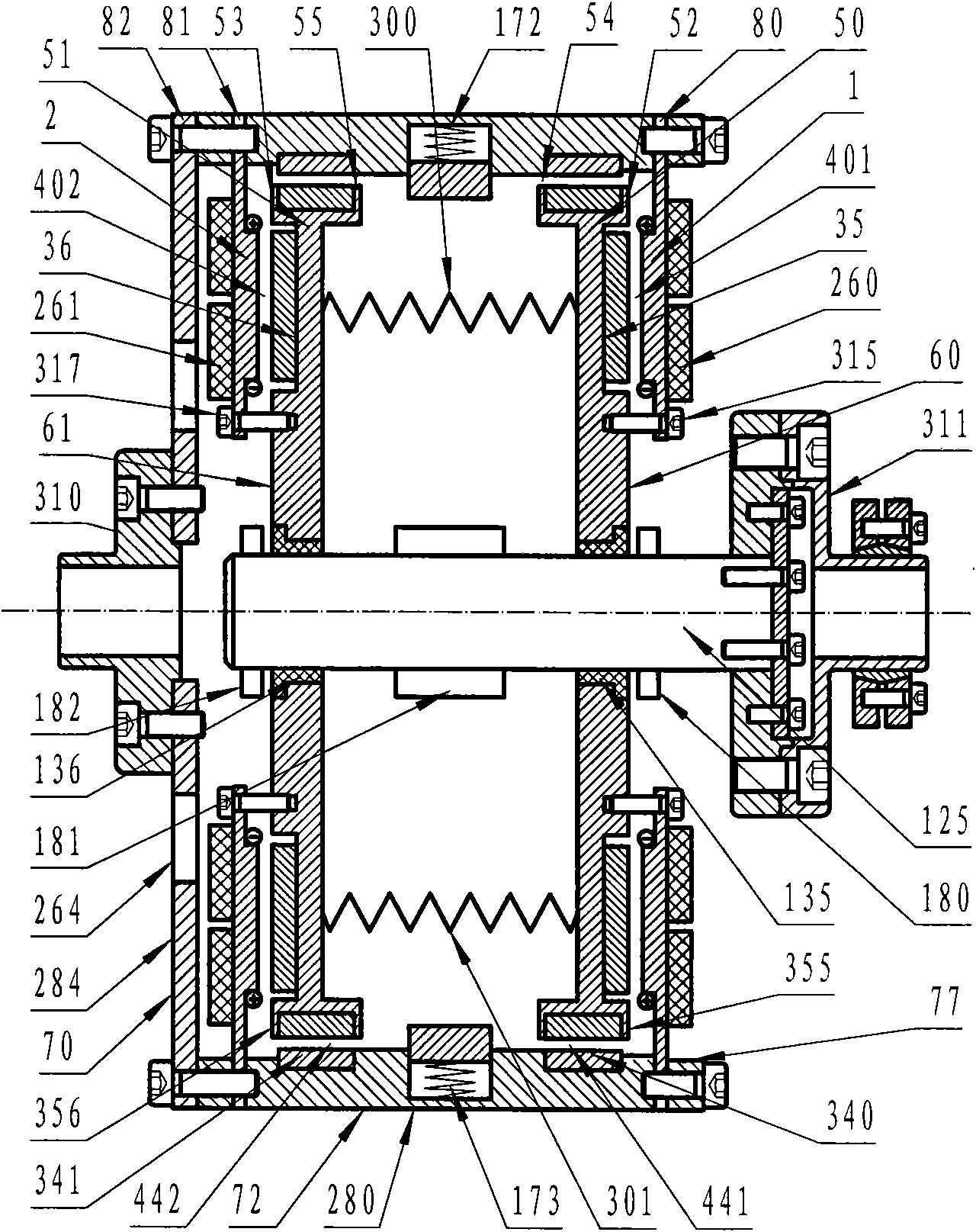
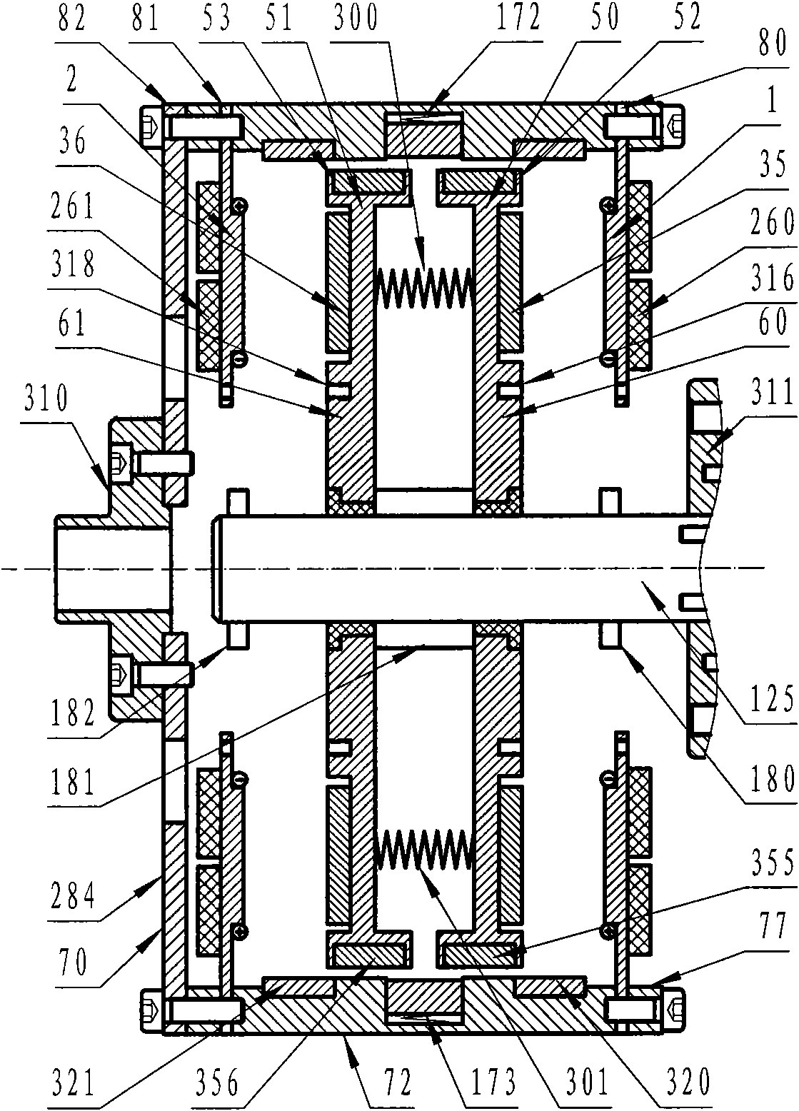
[0050] Such as figure 1 , figure 2 with image 3 As shown, it is a permanent magnetic coupling device of a drum type structure composed of two inner drums (50, 51) and an outer drum (70). The end walls (80, 81) of the outer drum are respectively provided with axial magnetic field armature winding disks (1, 2), and the end walls (60, 61) of the inner drum are respectively provided with axial magnetic field permanent magnet disks ( 35, 36), they are correspondingly coupled to form two axial magnetic field armature winding permanent magnetic coupling assemblies (401, 402), and the inner circumferential surface (77) of the outer drum wall (72) is provided with a radial magnetic field armature winding The discs (320, 321), the outer circumferential surfaces (54, 55) of the inner drum walls (52, 53) are provided with corresponding radial magnetic field permanent magnet discs (355, 356), and are respectively coupled to form two radial magnetic discs. The magnetic field metal cond...

Embodiment 2

[0054] Such as Figure 4 with Figure 5As shown, it is a permanent magnetic coupling device of a rotating drum structure composed of two inner rotating drums (550, 551) and an outer rotating drum (570). The end walls (580, 581) of the outer drum are respectively equipped with axial magnetic field grate type armature discs (510, 511), and the end walls (560, 561) of the inner drum are respectively equipped with axial magnetic permanent magnets. Discs (535, 536), which are respectively coupled to form two axial magnetic field grate type armature permanent magnetic coupling assemblies, and the inner peripheral surface (577) of the outer drum wall (572) is provided with a radial magnetic field permanent magnet disc ( 850,851), the outer circumferential surface (554,555) of the inner drum wall (552,553) radial magnetic field permanent magnet discs (855,856), and respectively correspondingly coupled to form a radial magnetic field double permanent magnetic coupling assembly; The g...

Embodiment 3

[0057] Such as Image 6 with Figure 7 As shown, it consists of axial magnetic field armature winding disks (1001, 1002) and axial magnetic field permanent magnet disks (1035, 1036) respectively coupled to form axial magnetic field armature winding permanent magnetic coupling assemblies (1001 and 1035, 1002 and 1036) A permanent magnetic coupling device with a turntable structure arranged back to back; the active permanent magnetic coupling turntable coupling mechanism is composed of a cage wall (1280) and a cage end wall (1284), and the cage end wall (1284) is connected to the drive shaft The couplings (1310) are connected; the passive permanent magnetic coupling turntable coupling mechanism consists of the turntable end wall (1060, 1061), the rolling screw auxiliary nut (1154, 1155) on the turntable end wall, the rolling screw auxiliary screw ( 1152, 1153), the slide bar hole on the end wall (1060, 1061) of the turntable not shown in the figure and its shaft sleeve and the ...


PUM


Abstract

The invention discloses a transmission shaft permanent magnet coupling drive and speed regulation device capable of adjusting magnetic torque, which has a turntable type, barrel type or turntable and barrel combined structure. The device consists of at least one set of axial magnetic field permanent magnet coupling component or/and radial magnetic field permanent magnet coupling component, at least one pair of diving permanent magnet coupling turntable coupling shaft mechanisms which are fit with a driving turntable in the permanent magnet coupling component, a corresponding driving shaft coupling, at least one pair of driven permanent magnet coupling turntable coupling shaft mechanisms which are fit with a driven permanent magnet coupling turntable in the permanent magnet coupling component, a corresponding driven shaft coupling, a pair of permanent magnet coupling turntable air gap and coupling area adjusting mechanisms and a pair of integrated assembling mechanisms which ensures that the system is an integrated structure and is convenient to package, transport and install. The device is applicable in the technical field of transmission shaft coupling drive, the technical field of load speed regulation and the field of power dragging.

Description

technical field [0001] The invention relates to the technical field of transmission shaft coupling drive, the technical field of load speed regulation and the field of power drag, in particular to a transmission shaft permanent magnetic coupling transmission and speed regulation device with adjustable magnetic torque. Background technique [0002] Around us, there are many fields involving transmission shaft coupling drive and speed regulation. In various transportation tools such as automobiles, trains, ships and airplanes, in almost various industrial occasions, and in people's production and life. Most of the common equipment driven by electric motors and internal combustion engines will use transmission shaft coupling drive and speed regulation technology, and there are various related technical solutions. Because the application field is very extensive and complicated, the background technology involved in the present invention only focuses on the field of motor drive f...

Claims


Application Information

Patent Timeline
Patent Type & Authority Applications(China)
IPC IPC(8): H02K49/10
CPCH02K49/108H02K2213/09H02K49/02H02K21/026
Inventor 林贵生
Owner 北京麦格纳传动科技有限公司
Why Eureka
Try Eureka