Barrel permanent magnet coupling capable of adjusting coupling space and area of air gap magnetic field

A technology of permanent magnet coupling and air gap magnetic field, applied in the direction of permanent magnet clutch/brake, electric brake/clutch, electrical components, etc., it can solve the problem that the power cannot be made too large, the permanent magnet coupling and the governor cannot be adjusted automatically Air gap spacing, low efficiency of permanent magnet coupling drive, etc.

Inactive Publication Date: 2011-03-30
北京麦格纳传动科技有限公司
View PDF2 Cites 27 Cited by
  • Summary
  • Abstract
  • Description
  • Claims
  • Application Information

AI Technical Summary

Problems solved by technology

Due to the limitations of their structure and technical solutions, there are many deficiencies in the technical performance of their products, which need to be improved and overcome. It mainly has the following deficiencies: ① Only a single double permanent magnetic coupling component or axial metal conductor permanent For magnetic coupling components, the power capacity per unit volume of the product is limited to a certain extent, and the power cannot be made too large; ②Permanent magnetic coupling and the governor itself cannot automatically adjust the air gap distance to achieve the purpose of speed regulation, and must be configured with another actuator or device. It is a purely mechanical transmission shaft coupling and speed-adjusting transmission device to realize air gap spacing adjustment. Under the background of the current mechatronics technology is very advanced and reliable, non-mechatronics products can no longer adapt to high reliability, high Accuracy, timely follow-up, and intelligent requirements; ③ Due to the limitation of the working principle of permanent magnetic coupling, the efficiency of permanent magnetic coupling drive is low. Under the conditions of the size of magnetic coupling components, air gap spacing, shaft speed and speed difference , the magnetic torque power that can be provided per unit volume is still relatively small, and the heat generation is relatively large, so that the design and manufacture of super-high-power permanent magnetic coupling and governor are still limited by cost and technical bottlenecks; The technology needs to be improved, and the heat dissipation technology is also the technical bottleneck for improving the transmission power capacity per unit volume of the permanent magnetic coupling device. One of the technical supports for long-term safe operation. According to investigations, at present, under the condition of 750 rpm, the maximum power of the air-cooled type can only reach about 130 kilowatts, and under the condition of 1500 rpm, the maximum power of the air-cooled type can only do To about 300 kilowatts, its popularization and application are greatly limited, the main reason has a lot to do with the heat dissipation problem; ⑤The mechanical transmission mechanism used to adjust the air gap spacing in the product has inherent technical limitations and shortcomings, especially for the design In a system with two or more magnetically coupled turntable or drum units, the transmission link has many mechanisms, there are transmission gaps between mechanisms, poor reliability, insufficient direct adjustment execution, and slow speed, etc., making the above products cannot be used Occasions that require high speed regulation follow-up and speed regulation accuracy, such as the speed regulation occasions of large boiler feed water pumps in power plants, etc.; ⑥The product does not have intelligent automation and intelligent control functions, let alone soft start and abnormal load operation The user-friendly handling of the situation, can not be personalized parameter settings for different load characteristics and operating conditions, which is greatly limited in many applications; ⑦ Due to the single product structure, it is limited in many application fields, currently only in the field of motor drive Application; ⑧The product is not integrated with the packaging and transportation structure of the whole machine, and more complicated parts and components are required to be installed at the product installation site. It is uneven and cannot guarantee the quality and technical performance of the whole machine. It is necessary to design the structure of the product and its associated integrated assembly mechanism. occur

Method used


Image

  • Barrel permanent magnet coupling capable of adjusting coupling space and area of air gap magnetic field
  • Barrel permanent magnet coupling capable of adjusting coupling space and area of air gap magnetic field
  • Barrel permanent magnet coupling capable of adjusting coupling space and area of air gap magnetic field

Examples


Embodiment 1

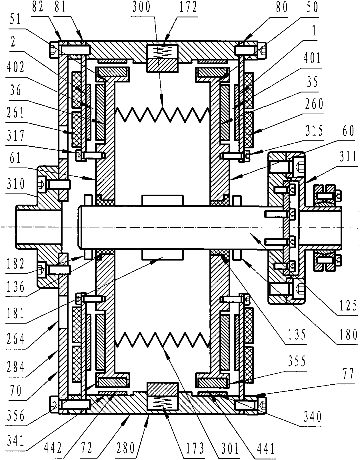
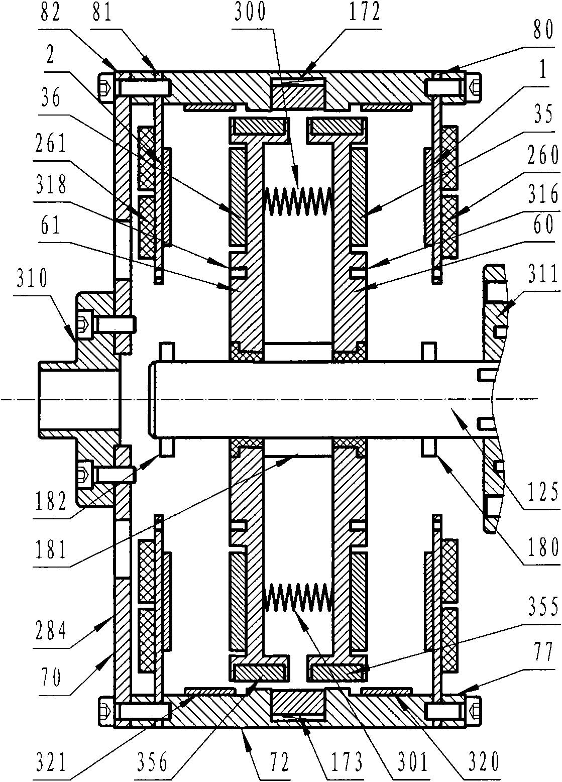
[0050] Such as figure 1 , figure 2 and image 3 As shown, it is a permanent magnetic coupling shaft coupling of a drum type structure composed of two inner drums (50, 51) and an outer drum (70). The end walls (80, 81) of the outer drum are respectively provided with axial magnetic field metal conductor disks (1, 2), and the end walls (60, 61) of the inner drum are respectively provided with axial magnetic field permanent magnet disks (35 , 36), they are respectively correspondingly coupled to form two axial magnetic field metal conductor permanent magnetic coupling assemblies (401, 402), and the inner peripheral surface (77) of the outer drum wall (72) is provided with a radial magnetic field metal conductor disk (320 , 321), the outer circumferential surface (54, 55) of the inner drum wall (52, 53) is provided with a corresponding radial magnetic field permanent magnet disk (355, 356), and is respectively correspondingly coupled to form two radial magnetic field metal cond...

Embodiment 2

[0054] Such as Figure 4 and Figure 5As shown, it is a permanent magnetic coupling shaft coupling of a drum type structure composed of two inner drums (550, 551) and an outer drum (570). The end walls (580, 581) of the outer drum are respectively provided with axial magnetic field metal conductor disks (510, 511), and the end walls (560, 561) of the inner drum are respectively provided with axial magnetic field permanent magnet disks (535 , 536), they are correspondingly coupled to form two axial magnetic field metal conductor permanent magnetic coupling components, the inner peripheral surface (577) of the outer drum wall (572) is provided with radial magnetic field metal conductor disks (850, 851), inner The outer peripheral surfaces (554, 555) of the drum walls (552, 553) are radial magnetic field permanent magnet disks (855, 856), and are respectively coupled to form a radial magnetic field metal conductor permanent magnetic coupling assembly; air gap spacing and couplin...

Embodiment 3

[0057] Such as Figure 6 and Figure 7 As shown, it consists of axial magnetic field metal conductor disks (1001, 1002) and axial magnetic field permanent magnet disks (1035, 1036) respectively coupled to form axial magnetic field metal conductor permanent magnetic coupling assemblies (1001 and 1035, 1002 and 1036) A permanent magnetic coupling coupling with a turntable structure arranged back to back. In addition, there are radial magnetic field metal conductor disks (1350, 1351) on the inner peripheral surface of the outer drum wall (1072), and the inner drum wall (1052 , 1051) are provided with radial magnetic field permanent magnet discs (1355, 1356) on the outer circumferential surface, and are respectively correspondingly coupled to form a radial magnetic field metal conductor permanent magnetic coupling assembly; the active permanent magnetic coupling turntable coupling mechanism consists of a cage wall (1280 ) and the machine cage end wall (1284), the machine cage end...


PUM


Abstract

A barrel permanent magnet coupling capable of adjusting coupling space and area of an air gap magnetic field is of rotary barrel structure or rotary disc/rotary barrel composite structure and comprises at least a group of axial magnetic field metal conductor permanent magnet coupling components or/and radial magnetic field metal conductor permanent magnet coupling components, at least a pair of driving permanent magnet coupling rotary disc coupling mechanisms adaptive to driving rotary discs in the permanent magnet coupling components and corresponding driving shaft couplings, at least a pair of driven permanent magnet coupling rotary disc coupling mechanisms adaptive to driven permanent magnet coupling rotary discs in the permanent magnet coupling components and corresponding driven shaft couplings, a pair of permanent magnet coupling rotary disc air gap space and coupling area adjusting mechanisms and a pair of integral assembling mechanisms ensuring the system to be integral structure so as to be convenient for packaging, transporting and installing. The coupling is suitable for the technical fields of transmission shaft coupling drive and load speed regulating and the field of power dragging.

Description

technical field [0001] The invention relates to the technical field of transmission shaft coupling drive, the technical field of load speed regulation and the field of power drag, in particular to a cylindrical permanent magnetic coupling coupling with adjustable air gap magnetic field coupling spacing and area. Background technique [0002] Around us, there are many fields involving transmission shaft coupling drive and speed regulation. In various transportation tools such as automobiles, trains, ships and airplanes, in almost various industrial occasions, and in people's production and life. Most of the common equipment driven by electric motors and internal combustion engines will use transmission shaft coupling drive and speed regulation technology, and there are various related technical solutions. Because the application field is very extensive and complicated, the background technology involved in the present invention only focuses on the field of motor drive for an ...

Claims


Application Information

Patent Timeline
Patent Type & Authority Applications(China)
IPC IPC(8): H02K49/10
CPCH02K49/108H02K2213/09H02K49/106
Inventor 余亚莉林贵生
Owner 北京麦格纳传动科技有限公司
Why Eureka
Try Eureka