
Cone drum for piston pusher centrifuge

A centrifuge and drum technology, applied in the direction of centrifuges, etc., can solve the problems of increasing the production cost of centrifuges, increasing maintenance costs, cost performance and hindering the development of multi-stage pusher centrifuges, etc., to achieve a wide range of use and low manufacturing and maintenance costs. Low, good dehydration effect

Inactive Publication Date: 2011-04-06
CHENGDU TIANBAO HEAVY IND
View PDF5 Cites 3 Cited by
  • Summary
  • Abstract
  • Description
  • Claims
  • Application Information

AI Technical Summary

Problems solved by technology

However, with the increase in the number of drum stages, the requirements for the manufacturing and assembly accuracy of the centrifuge have increased rapidly, which has increased the production cost of the centrifuge, and the maintenance cost in daily operation has also increased accordingly. important factor

Method used


Image

  • Cone drum for piston pusher centrifuge
  • Cone drum for piston pusher centrifuge

Examples


Embodiment 1

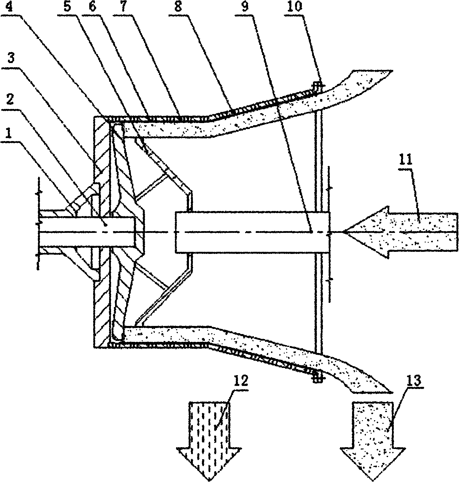
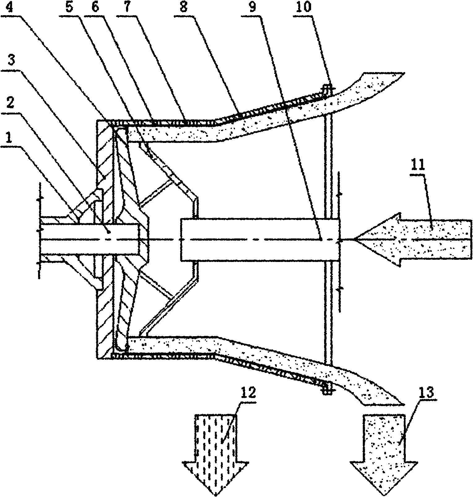
[0019] Such as figure 1 As shown, the cylindrical-cone drum used for the piston pusher centrifuge includes a wheel 3 connected to the main shaft 1, and the drum body is connected to the wheel with screws to form a drum. The drum body is composed of a cylindrical body 7 and a conical body. The 8 small ends are connected by a smooth transition. The push plate 4 is fixed on one end of the push rod 2. The push plate 4 and the push rod 2 run through the main shaft 1 and the drum body. The distributor 5 is connected to the push plate by several ribs. 4, the feed pipe 9 is fixed on the solid-liquid tank of the centrifuge, and passes into the hole of the distributor 5; when the column-cone-piston pusher centrifuge separates heavy alkali (NaHCO3), the water content of the suspension feed is 18 %, the average particle size of the solid phase is 80 to 90 microns, the semi-cone angle of the conical cylinder 8 can be 10°, and its large end is the discharge end; The porosity is 35%, and th...

Embodiment 2

[0021] Such as figure 1 As shown, the cylindrical-cone drum used for the piston pusher centrifuge includes a wheel 3 connected to the main shaft 1, and the drum body is connected to the wheel with screws to form a drum. The drum body is composed of a cylindrical body 7 and a conical body. The 8 small ends are connected by a smooth transition. The push plate 4 is fixed on one end of the push rod 2. The push plate 4 and the push rod 2 run through the main shaft 1 and the drum body. The distributor 5 is connected to the push plate by several ribs. 4, the feed pipe 9 is fixed on the solid-liquid tank of the centrifuge, and passes into the hole of the distributor 5; when the column-cone-piston pusher centrifuge separates the salt, the water content of the suspension feed is 70% to 80%. , the solid phase average particle size is 110 microns, the half-cone angle of the conical cylinder 8 is 8°, and its big end is the discharge end; %, and the inner circumferential surface of the cyl...


PUM


Abstract

The invention relates to a piston pusher centrifuge, in particular to a novel cone drum for a piston pusher centrifuge. The cone drum comprises a wheel disc connected with a main shaft, and a drum body is connected with the wheel disc by using screws to form the drum of the centrifuge. The drum body is formed by combining a cylindrical barrel and a conical barrel, and screen cloths are laid on the inner circumferential surfaces of the cylindrical barrel and the conical barrel. A pusher disc is fixed on one end of a push rod, the pusher disc and the push rod respectively penetrate in the main shaft and the drum body, a distributing device is connected to the pusher disc through a plurality of ribs, and a material inlet pipe is fixed on a solid and liquid tank of the centrifuge. The invention integrates the advantages of a centrifugal unloading centrifuge and the piston pusher centrifuge, and the centrifuge has the advantages of simple structure, low manufacturing and maintenance cost, large use range, improved centrifugation performance and reduced energy consumption.

Description

Technical field [0001] The invention relates to a piston pusher centrifuge, in particular to a novel column-cone drum for the piston pusher centrifuge. Background technique [0002] At present, the drum of the centrifugal discharge centrifuge is a conical cylinder, and the filter cake is automatically and continuously discharged from the drum from the small end to the large end under the centrifugal force along the cone surface in the conical drum, so there is no special The unloading mechanism has simple structure, low power consumption, and large processing capacity; but the centrifugal unloading centrifuge is very sensitive to changes in material characteristics and suspension concentration, and has poor adaptability. In addition, due to thin-layer filtration, the sieving effect is significant, and fine particles Large leakage. [0003] The piston pusher centrifuge is a filter centrifuge that uses the pusher disc to continuously push out the filter cake formed in the dru...

Claims


Application Information

Patent Timeline
Patent Type & Authority Applications(China)
IPC IPC(8): B04B7/08B04B7/16
Inventor 邓亲华邓翔王青宗
Owner CHENGDU TIANBAO HEAVY IND
Learn More