Combined type high and low pressure cylinder hydraulic end

A high-low pressure, compound technology, applied in liquid variable capacity machinery, piston pumps, machines/engines, etc., can solve the problems of complex structure, difficult installation, delaying assembly time, etc., to achieve simple installation structure and layout, pressure regulation Convenience, high design pressure effects

Active Publication Date: 2011-04-06
四川杰特机器有限公司
View PDF7 Cites 7 Cited by
  • Summary
  • Abstract
  • Description
  • Claims
  • Application Information

AI Technical Summary

Problems solved by technology

[0006] The fluid end of the existing four-cylinder reciprocating pressure test pump can only be installed in a dispersed manner because the four plungers are dispersedly arranged (see figure 1 There is a hydraulic end structure diagram of a four-cylinder reciprocating pressure test pump), in order to gather high-pressure water, it is necessary to set up a water collection body, and connect the water outlets with high-pressure hard pipes. In this way, not only the structure is complicated, but the installation is difficult, especially It is the connection seal of the high-pressure hard pipe. If there is a slight angle that is not bent in place or the size is wrong, the installation may not be sealed. When the product is checked and accepted, water leakage is found, and most of the parts can only be removed (maybe many parts have nothing to do with this leakage) , especially the high-pressure hard pipes can only be overhauled after they are completely disassembled, which delays assembly time

Method used


Image

  • Combined type high and low pressure cylinder hydraulic end
  • Combined type high and low pressure cylinder hydraulic end
  • Combined type high and low pressure cylinder hydraulic end

Examples


Embodiment Construction

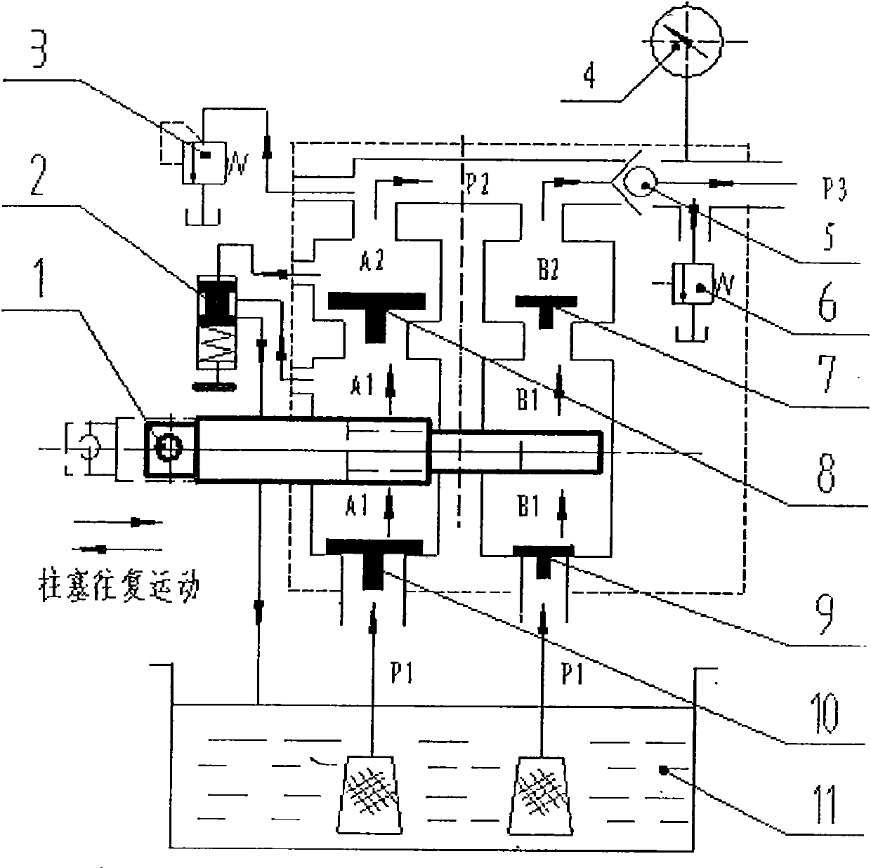
[0027] The working principle of the fluid end of the composite high and low pressure cylinder: see the principle of the fluid end of the composite high and low pressure cylinder figure 2 .

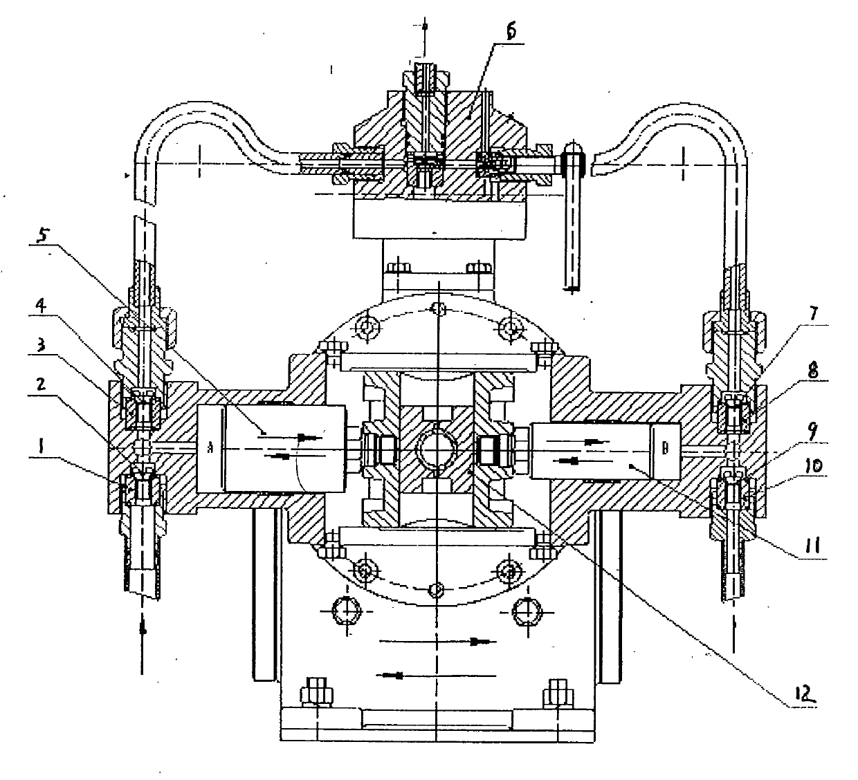
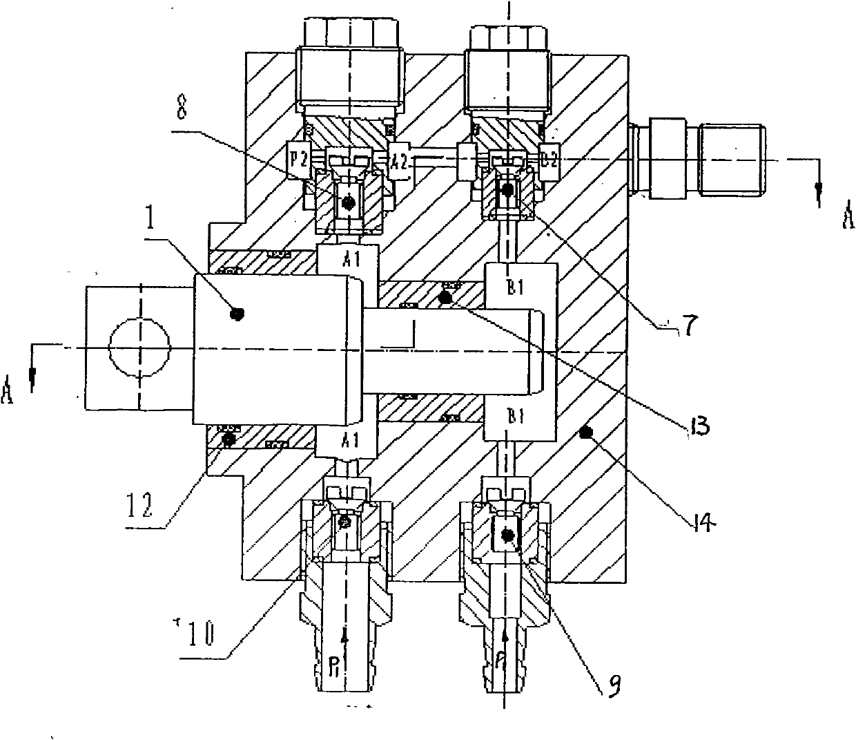
[0028] The rotary motion of the motor drives the stepped plunger 1 to reciprocate in the water tank through the transmission mechanism, so that the working volume of each working chamber changes continuously, and then the alternate suction and discharge process of the pump is realized.

[0029] When the stepped plunger is in the suction stroke (the dotted line position in the figure), the working volume in the water tank (A1 cavity and B1 cavity) increases, resulting in a partial vacuum, and the working medium in the water tank passes through a large flow rate under the action of atmospheric pressure. The water inlet valve 10 and the small flow water inlet valve 9 enter the working chamber (A1, B1). When the plunger is in the discharge stroke (the position of the solid line in the figure...


PUM


Abstract

The invention provides a combined type high and low pressure cylinder hydraulic end, which is used for solving the problems that the structure of the prior hydraulic end is complicated, the manufacturing cost of the existing hydraulic end is high, and the existing hydraulic end is inconvenient to install and maintain. Two combined cylinders are respectively matched with one stepped plunger (1); a high-flow low pressure chamber (A1) is connected with a low-pressure water inlet passageway P1 by a high-flow inlet valve (10); the high-flow low pressure chamber (A1) is communicated with a high-flow high pressure chamber (A2) by a high-flow inlet valve (8); the high-flow high pressure chamber (A2) is communicated with a working pressure passageway P3 by a high pressure water outlet passageway P2; a low-flow low pressure chamber B1 is connected with the low pressure water inlet passageway P1 by a low-flow inlet valve (9); a low-flow low pressure chamber B1 is connected with a low-flow high pressure chamber B2 by a low-flow outlet valve (7); the low-flow high pressure chamber B2 is connected with a working pressure passageway P3 by the high pressure water outlet passageway P2; and the upper end of the valve chest of a hydraulic control communication valve is connected with the high pressure water outlet passageway P2, the lower end of a valve plug is connected with a pressure-regulating spring, and the upper and lower holes on the side wall of the valve chest are respectively connected with the high-flow low pressure chamber (A1) and the passageway of a water intake box (11).

Description

Technical field: [0001] The invention relates to the fluid end of a four-cylinder reciprocating pressure test pump. Background technique: [0002] The hydraulic end of the four-cylinder reciprocating pressure test pump is mainly used for the pressure test of valves, blowout preventers and other products of oil field users that need to detect the working pressure, and is specially designed according to the characteristics of the user's hydraulic test of the test piece. For example: most of the tested pieces need to be quickly filled and boosted in the initial stage of the pressure test to shorten the pressure test time and have a large flow rate. When the pressure exceeds 1.6MPa (this pressure can be adjusted), in order to make the pressure test process If it can be carried out more smoothly and slowly, the flow rate will automatically decrease, so the pump has two kinds of flow rates at high and low pressure, and it can be changed automatically. Therefore, this type of four-...

Claims


Application Information

Patent Timeline
Patent Type & Authority Applications(China)
IPC IPC(8): F04B9/10
Inventor 李文陈建蒋金泉邱富彬魏星吴家红曾维聪周进
Owner 四川杰特机器有限公司
Why Eureka
Try Eureka