Dual-sliding vane rotary compressor, control method and application thereof
A rotary compressor and double-sliding vane technology, applied in the field of rotary compressors, can solve problems such as large sliding losses, achieve low production costs, reduce sliding losses, and improve compressor efficiency
- Summary
- Abstract
- Description
- Claims
- Application Information
AI Technical Summary
Problems solved by technology
Method used
Image
Examples
no. 1 example
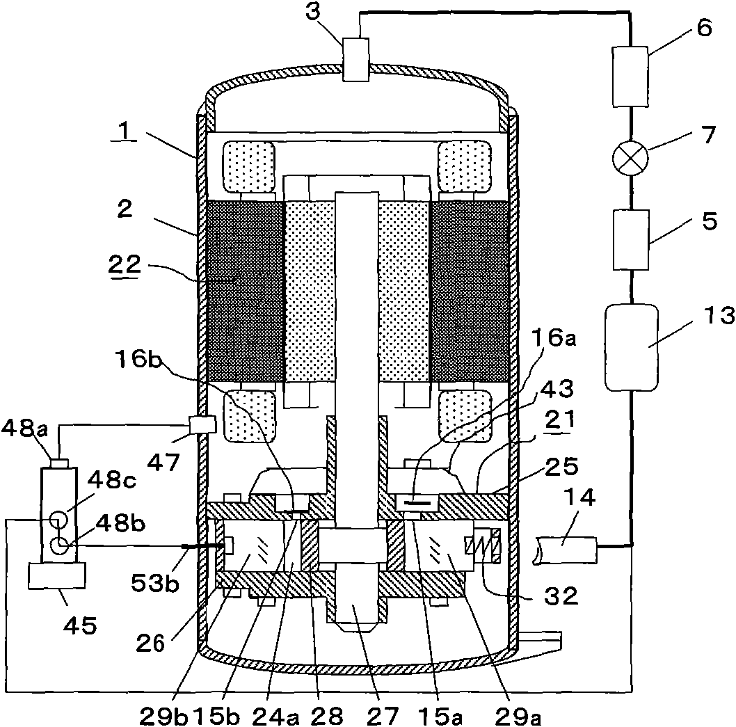
[0040] see figure 1 , shows the internal structure of the double vane rotary compressor of the present invention and a refrigeration cycle equipped with the compressor. Hereinafter, the double-vane rotary compressor is abbreviated as the rotary compressor 1 .
[0041] The rotary compressor 1 is composed of a compression mechanism unit 21 installed inside the hermetic casing 2, and an electric motor unit 22 arranged on the top thereof. The compression mechanism unit 21 is composed of a cylinder 23, a piston 28, a crankshaft 27, a main bearing 25, a sub bearing 26, a muffler 43, and the like, as in a normal single-cylinder rotary compressor. The cylinder 23 has two slides: the first slide 29a and the second slide 29b, and two discharge holes: the first discharge hole 15a and the second discharge hole 15b.
[0042] A three-way valve 45 for control is arranged outside the rotary compressor 1 in order to stop the operation of the second slide plate 29b or cancel the stop.
[0043]...
no. 2 example
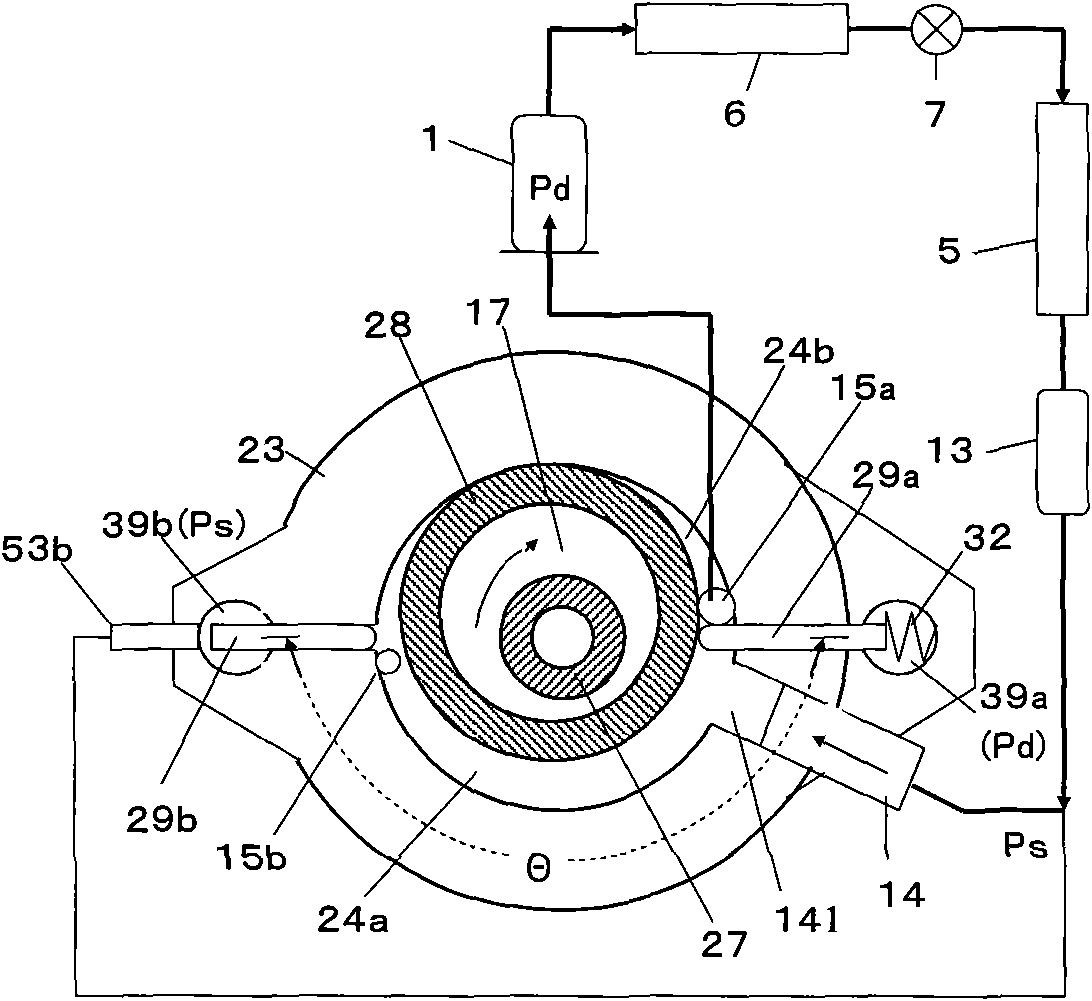
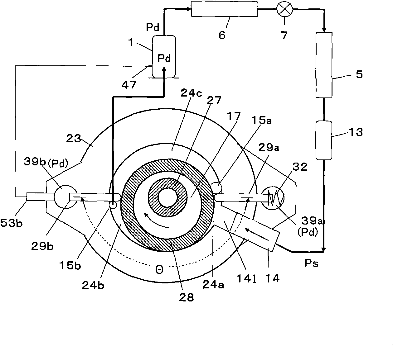
[0079] see Image 6 , the second example shows image 3 In the S mode described in , the first sliding plate 29a is stopped, and the sliding loss generated by the reciprocating motion of the first sliding plate 29a and the sliding loss generated by the contact between the tip of the first sliding plate 29a and the piston 28 are zero. means. In the S mode in the second embodiment, while the second vane cavity 39b is taken as the high-pressure side Pd, the first vane 39a is taken as the low-pressure side Ps.
[0080] In this way, after determining the pressure of the slide cavity, the second slide 29b can be in contact with the piston 28, but the first slide 29a cannot be in contact with the piston 28. As a result, S-mode operation is realized. When switching from the S mode to the P mode, the second vane chamber 39b is regarded as the low pressure side Ps, and the first vane chamber 39a is regarded as the high pressure side Pd. As a result, with the first embodiment's fig...
no. 3 example
[0091] The motor part 21 of the rotary compressor 1 of the first embodiment or the second embodiment is changed to an inverter type motor part, and after the displacement control and the number of revolutions control are combined, the disclosure disclosed in the first embodiment or the second embodiment can be expanded. application of technology. The third embodiment is related to a double vane type inverter type rotary compressor formed by these combinations.
[0092] Figure 9 , shows the relationship between the number of revolutions (the horizontal axis in the figure) and the cooling capacity (the left vertical axis in the figure) of the double-sliding vane frequency conversion rotary compressor, and shows the motor efficiency caused by the number of revolutions (the horizontal axis in the figure right vertical axis). Generally speaking, the motor efficiency of the inverter type rotary compressor is the highest around 60rps, and the efficiency deteriorates sharply after ...
PUM
 Abstract
Description
Claims
Application Information
 - R&D
- Intellectual Property
- Life Sciences
- Materials
- Tech Scout
- Unparalleled Data Quality
- Higher Quality Content
- 60% Fewer Hallucinations
Browse by: Latest US Patents, China's latest patents, Technical Efficacy Thesaurus, Application Domain, Technology Topic, Popular Technical Reports.
© 2025 PatSnap. All rights reserved.Legal|Privacy policy|Modern Slavery Act Transparency Statement|Sitemap|About US| Contact US: help@patsnap.com


