
Unidirectional overrunning clutch gear shift mechanism

A technology that surpasses clutch and second gear. It is used in mechanical equipment, gear transmissions, components with teeth, etc., and can solve problems such as off-gear, flameout, engine lost rotation, and slow response to speed changes.

Inactive Publication Date: 2012-11-21
SINONEWENERGY SUZHOU TECH
View PDF0 Cites 0 Cited by
  • Summary
  • Abstract
  • Description
  • Claims
  • Application Information

AI Technical Summary

Problems solved by technology

The manual transmission relies on the driver to change the speed manually, which requires very high experience of the driver. The level of the driver directly affects the safety of driving and the service life of the vehicle. For inexperienced drivers, when the speed changes suddenly, It will cause the engine to run under unsteady conditions, and it is prone to problems such as off-gear and flameout; the transmission ratio rotation and shifting of the automatic transmission are carried out automatically, and the conversion of each gear of the mechanical transmission is based on reflecting the engine load and The vehicle speed signal system is used to control the actuators of the shift system. The driver only needs to manipulate the accelerator pedal to control the vehicle speed. However, the automatic transmission still needs to go through two processes of separation and engagement when shifting gears. The driving force is cut off before the gear, so you can obviously feel the frustration, and the mechanism is complicated and difficult to repair. At the same time, due to the limitation of the sensor technology, the response to the speed change is slow, and it is not as sensitive as the manual gear; the continuously variable transmission can realize the continuous transmission ratio. Change, so as to get the best match between the transmission system and the engine operating conditions, theoretically improve the fuel economy and power of the vehicle, improve the driver's handling convenience and the passenger's ride comfort, so it is ideal in theory Motor vehicle transmissions, therefore, are widely used in existing scooters. However, CVTs are basically used in small vehicles such as motorcycles to use belt drives, and the load torque is limited. When the torque is large, the engine will lose Turning phenomenon directly affects the power, economy and safety of the car

Method used


Image

  • Unidirectional overrunning clutch gear shift mechanism
  • Unidirectional overrunning clutch gear shift mechanism
  • Unidirectional overrunning clutch gear shift mechanism

Examples


Embodiment 1

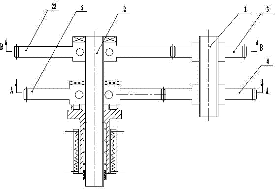
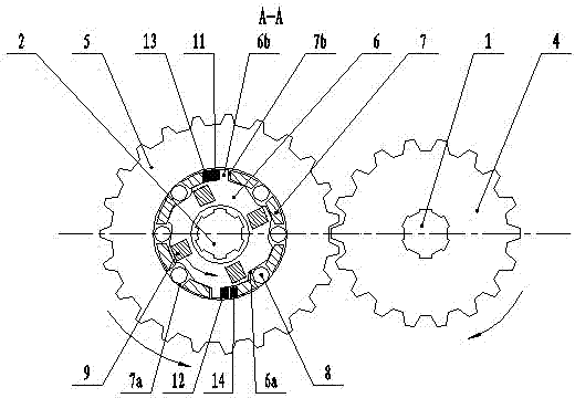
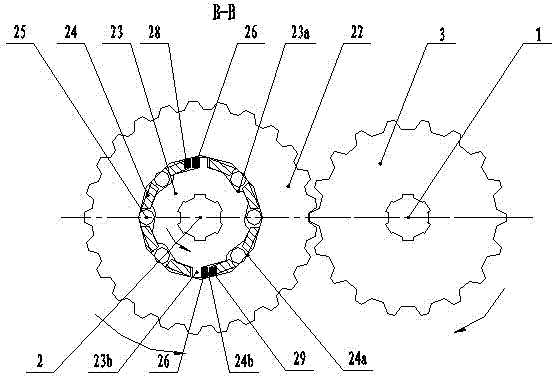
[0035] please join Figure 5 , Figure 6 , Figure 7 , Figure 14 and Figure 15: the second gear driven unidirectional device includes a second gear driven gear 5 meshing with the second gear driving gear 4, and the left part of the second gear driven gear 5 is mounted on the driven shaft 2 via a bearing, The center of the right part of the second gear driven gear 5 is equipped with a second gear driven cam 6, and the second gear driven cam 6 is looped on the driven shaft 2, and the second gear driven cam 6 and the second gear A second gear driven floating sleeve 7 is installed between the inner walls of the driven gear 5, and a group of second gear driven cam curved surfaces 6a and two second gear driven cams 6b are arranged on the outer circumference of the second gear driven cam 6. , the two second-gear driven cams 6b and the second-gear driven cam curved surface 6a are evenly distributed on the outer circumference of the second-gear driven cam 6, and the two second-ge...

Embodiment 2

[0037] please join Figure 8 , Figure 9 , Figure 10 , Figure 14 and Figure 15 : the second gear driven unidirectional device includes a second gear driven gear 5 meshing with the second gear driving gear 4, and the left part of the second gear driven gear 5 is mounted on the driven shaft 2 via a bearing, The center of the right part of the second gear driven gear 5 is equipped with a second gear driven cam 6, and the second gear driven cam 6 is looped on the driven shaft 2, and the second gear driven cam 6 and the second gear A second gear driven floating sleeve 7 is installed between the inner walls of the driven gear 5, and a group of second gear driven cam curved surfaces 6a and two second gear driven cams 6b are arranged on the outer circumference of the second gear driven cam 6. , the two second-gear driven cams 6b and the second-gear driven cam curved surface 6a are evenly distributed on the outer circumference of the second-gear driven cam 6, and the two second-...

Embodiment 3

[0039] please join Figure 11 , Figure 12 , Figure 13 , Figure 14 and Figure 15 : the second gear driven unidirectional device includes a second gear driven gear 5 meshing with the second gear driving gear 4, and the left part of the second gear driven gear 5 is mounted on the driven shaft 2 via a bearing, The center of the right part of the second gear driven gear 5 is equipped with a second gear driven cam 6, and the second gear driven cam 6 is looped on the driven shaft 2, and the second gear driven cam 6 and the second gear A second gear driven floating sleeve 7 is installed between the inner walls of the driven gear 5, and a group of second gear driven cam curved surfaces 6a and two second gear driven cams 6b are arranged on the outer circumference of the second gear driven cam 6. , the two second-gear driven cams 6b and the second-gear driven cam curved surface 6a are evenly distributed on the outer circumference of the second-gear driven cam 6, and the two secon...


PUM


Abstract

The invention discloses a unidirectional overrunning clutch gear shift mechanism, which comprise a driving shaft and driven shaft, wherein a first-shift driving gear and a second-shift driving gear are sleeved on the driving shaft, a first-shift driven one-way clutch is sleeved on the driven shaft, the first-shift driven gear of the first-shift driven one-way clutch is meshed with the first-shiftdriving gear, the first-shift driving gear drives the first-shift driven one-way clutch to rotate, and the first-shift driven one-way clutch drives the driven shaft to rotate; and a second-shift driven one-way / two-way clutch is sleeved on the driven shaft, the second-shift driving gear is meshed with a second-shift driven gear in the second-shift driven one-way / two-way clutch, the second-shift driving gear drives the second-shift driven one-way / two-way clutch to rotate, and the second-shift driven one-way / two-way clutch drives the driven shaft to rotate. The mechanism is simple and novel in structure and can realize gear shift reliably through the one-way clutch and the one-way / two-way clutch. The mechanism has the advantages of simple structure, small volume, easy maintenance and low cost.

Description

technical field [0001] The invention relates to an engine auxiliary device, in particular to a co-directional overrunning clutch gear shifting mechanism capable of realizing co-directional clutch overrunning gear shifting. Background technique [0002] In the prior art, various automobiles, motorcycles, and electric bicycle transmissions are of a great variety, but they are inseparable from each other. The transmissions mainly include manual transmissions, automatic transmissions and continuously variable transmissions. The manual transmission relies on the driver to change the speed manually, which requires very high experience of the driver. The level of the driver directly affects the safety of driving and the service life of the vehicle. For inexperienced drivers, when the speed changes suddenly, It will cause the engine to run under unsteady conditions, and it is prone to problems such as off-gear and flameout; the transmission ratio rotation and shifting of the automat...

Claims


Application Information

Patent Timeline
Patent Type & Authority Patents(China)
IPC IPC(8): F16H3/10F16H59/04
CPCF16H3/003
Inventor 左佳奇
Owner SINONEWENERGY SUZHOU TECH
Learn More