LED bulb

A technology for LED bulbs and lampshades, which is applied to lighting devices, cooling/heating devices of lighting devices, light sources, etc., can solve problems such as cost increase, circuit board failure, low production efficiency, etc. The effect of improving production efficiency

Inactive Publication Date: 2011-04-06
TIANJIN JINYA ELECTRONICS
View PDF0 Cites 10 Cited by
  • Summary
  • Abstract
  • Description
  • Claims
  • Application Information

AI Technical Summary

Problems solved by technology

[0011] One is to imitate the structure of an incandescent lamp, and directly place the circuit board inside the lamp cap, which will lengthen the lamp cap and shorten the length of the radiator, which greatly affects the heat dissipation effect of the LED and makes the LED easy to damage. Affect the service life of the bulb;
[0012] The other is that there is a groove at the lower end of the radiator, and then directly put the circuit board into the bulb from the bottom of the radiator, and then connect the lamp holder. The disadvantage of this is that the circuit board will be left and right in the groove of the radiator. Shaking, it is likely to damage the circuit board when transporting or loading and unloading the bulb, which will cause the circuit board to fail and damage the bulb. What is more dangerous is that if the connector or wire of the circuit board falls off and touches the radiator, the outer wall of the bulb will be damaged. It will be charged, which will cause personal injury, and the safety performance cannot be guaranteed.
[0013] In addition, the current production and assembly of LED light bulbs is basically manual operation. Due to the simple design of general light bulbs, there is no structure for quickly fixing positions between parts, which makes the production efficiency low and it is difficult to achieve large-scale mass production. The standard requires that the workers are very random, so that the quality of the bulbs cannot be guaranteed, especially for new workers, they will also damage the accessories of the bulbs due to operational errors during installation, which will increase the production cost and cause damage to the enterprise. many unnecessary losses

Method used


Image

  • LED bulb
  • LED bulb
  • LED bulb

Examples


Embodiment Construction

[0037] Embodiments of the present invention are described in further detail below in conjunction with the accompanying drawings:

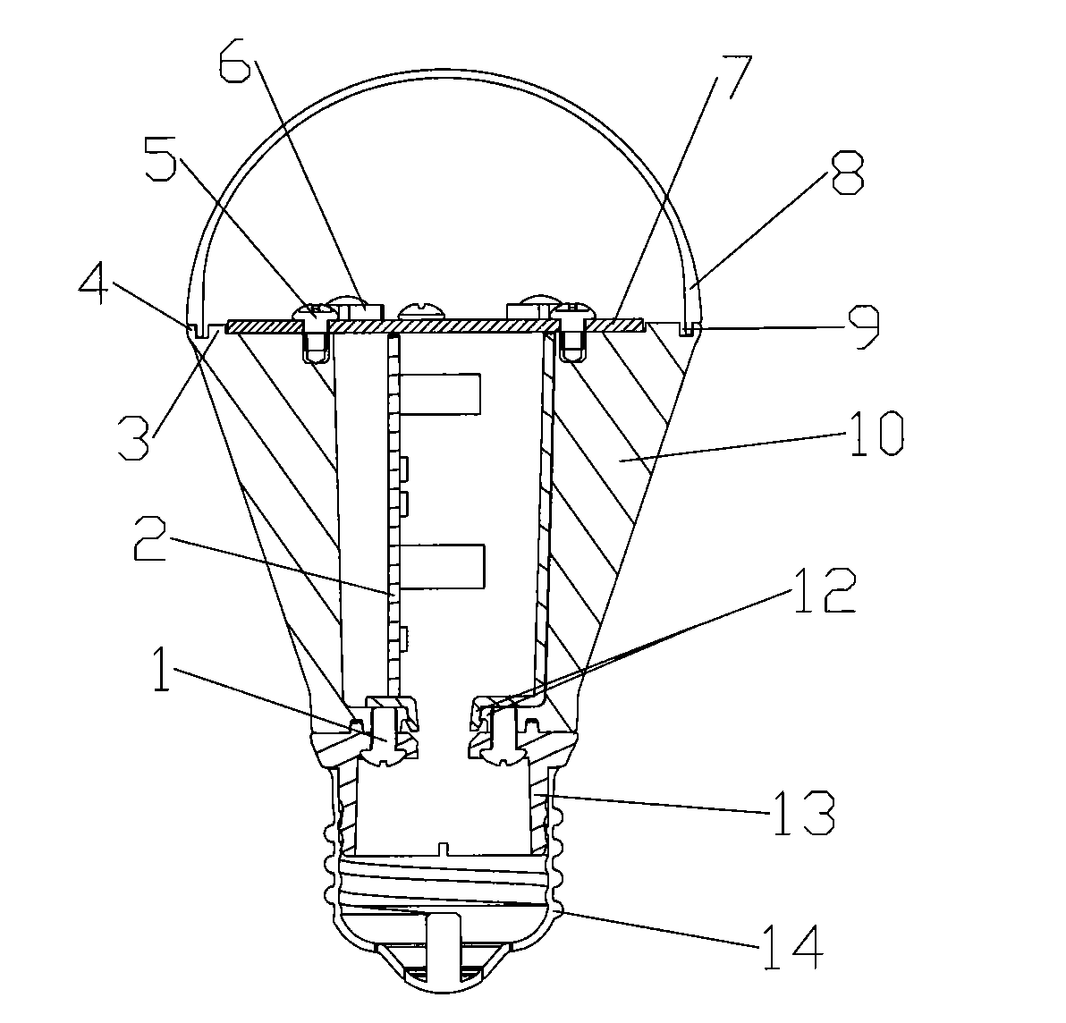
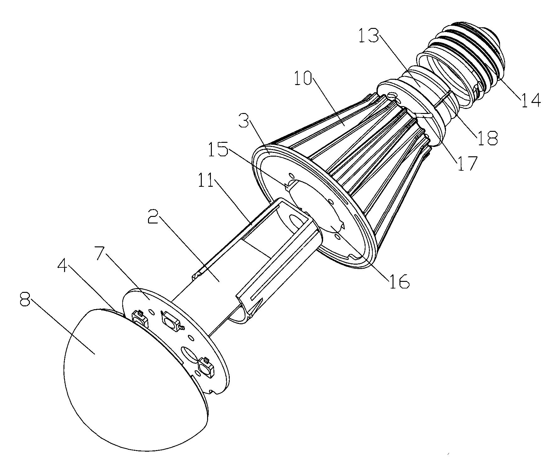
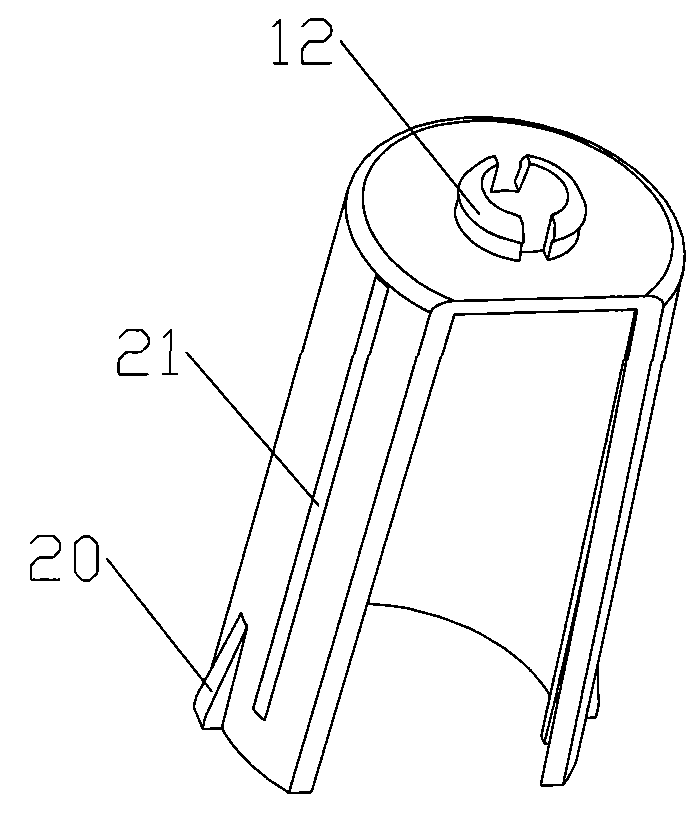
[0038] like Figure 1-6 As shown, 1 is a screw, 2 is a circuit board, 3 is a rib, 4 is a protrusion, 5 is a screw, 6 is an LED, 7 is an aluminum substrate, 8 is a lampshade, 9 is a groove, 10 is a heat sink, and 11 is a Sheath, 12 is a hook, 13 is a connecting piece, 14 is a lamp cap, 15 is a wedge-shaped groove, 16 is an inner cavity, 17 is a through groove, 18 is an outlet groove, 19 is a shallow groove, 20 is a wedge-shaped block, and 21 is a slide Groove, 22 is protrusion.

[0039] The LED light bulb of the present invention comprises lampshade 8, radiator 10, aluminum substrate 7, LED6, circuit board 2, connector 13 and lamp cap 14, wherein LED6 is welded on the aluminum substrate 7, lampshade 8 and radiator 10 are connected with screw 5 , the radiator 10 and the connector 13 are connected by screws 1, and the connector 13 and the lamp cap 1...


PUM


Abstract

The invention discloses a light emitting diode (LED) bulb and aims to provide the LED bulb which has high anti-shock performance and high radiating performance and is convenient to install and maintain. The LED bulb of the invention comprises a lamp shade, a radiator, an aluminum base, an LED, a circuit board, a connecting piece and a lamp holder, wherein the lamp shade is connected with the radiator; the radiator is connected with the connecting piece; the connecting piece is connected with the lamp holder; the LED is welded on the aluminum base; a cavity is reserved in the radiator; the opening of the cavity is upward; a sheath is arranged in the cavity of the radiator; hooks are arranged at the positions corresponding to the lower end of the sheath and the lower end of the radiator so as to form a fastener structure; and the sheath and the radiator can be connected with each other through the fastener structure. The LED bulb has high anti-shocking performance and radiating performance, is convenient to install and maintain, and is a regeneration product of the convention LED bulb.

Description

technical field [0001] The invention relates to the technical field of lighting equipment, in particular to an LED lighting bulb. Background technique [0002] LED is the abbreviation of English light emitting diode (light emitting diode). LED is a semiconductor that can convert electrical energy into visible light. With many advantages such as long life, high luminous efficiency, no radiation, and low power consumption, LEDs are gradually introduced into lighting fixtures as light sources with the introduction of energy-saving and green lighting concepts. [0003] At present, incandescent bulbs or fluorescent tubes are the main light-emitting sources used in daily lighting such as daily bulbs and table lamps. However, the electro-optic conversion efficiency of incandescent bulbs and fluorescent tubes is relatively low, and their heat is large and their service life is long. Short, generally only about 3000 hours. [0004] The LED can overcome the above shortcomings, and i...

Claims


Application Information

Patent Timeline
Patent Type & Authority Applications(China)
IPC IPC(8): F21S2/00F21V29/00F21V17/10F21Y101/02F21V29/503F21V29/70
Inventor 曹军鹏杨士文马凤午
Owner TIANJIN JINYA ELECTRONICS
Why Eureka
Try Eureka