Heat-relieving device for industrial emission

A heat-dissipating and industrial technology, applied in the field of industrial emission treatment devices, can solve problems such as thermal pollution that cannot be completely solved

Inactive Publication Date: 2011-04-06
张宏生
View PDF1 Cites 4 Cited by
  • Summary
  • Abstract
  • Description
  • Claims
  • Application Information

AI Technical Summary

Problems solved by technology

This structure can only transfer the heat in the flue gas to the water, and the discharged cooling water still contains a lot of heat, which still cannot completely solve the problem of heat pollution

Method used


Image

  • Heat-relieving device for industrial emission
  • Heat-relieving device for industrial emission
  • Heat-relieving device for industrial emission

Examples


Embodiment Construction

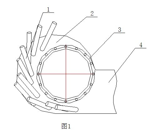
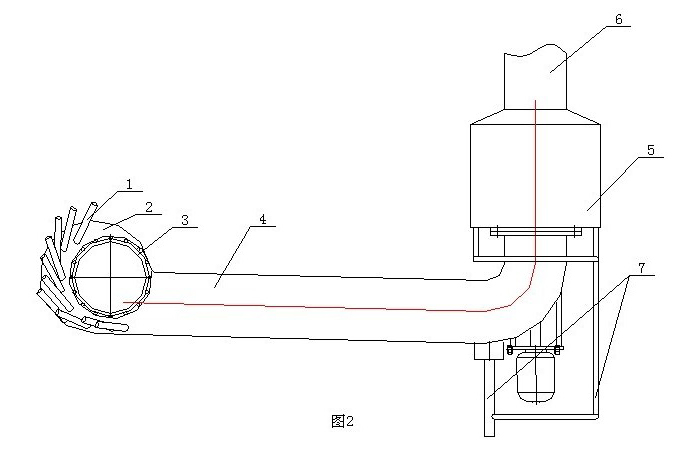
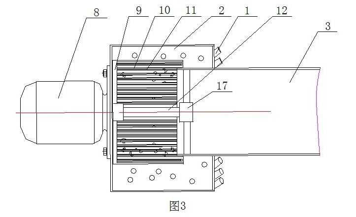
[0019] Such as figure 1 , figure 2 As shown, the present invention is a heat dissipation device for industrial discharge, which includes a casing 2 with a discharge pipe 3 and a discharge pipe 4, a motor 8 is fixedly installed on the side wall of the casing 2, and a motor 8 is fixed on the side wall of the discharge pipe. 3. A bearing 17 is fixedly installed inside, and the front end of the output shaft 12 of the motor 8 is inserted through the inner hole of the bearing 17, which can ensure the stability of the output shaft 12 of the motor 8 when it rotates. On the output shaft 12 of the motor 8, a wind wheel 9 with blades 10 on the side wall is fixedly installed. On the outer wall of the housing 2, a plurality of air guide pipes 1 communicating with the inner cavity of the housing 2 are arranged. When the wind wheel 9 When rotating, negative pressure will be generated in the inner cavity of the casing 2, so that the cold air from the outside is introduced into the casing 2 ...


PUM


Abstract

The invention relates to a heat-relieving device for industrial emission, comprising a shell with an immission pipe and an emission pipe, wherein the side wall of the shell is fixedly installed with a motor, a bearing is fixedly installed in the immission pipe, the front end of an output shaft of a motor is inserted to an inner hole of the bearing, a wind wheel with vanes on the side wall is fixedly installed on the output shaft of the motor, a plurality of air guide pipes communicated with an inner cavity of the shell are arranged on the outer wall of the shell, and the orientations of the air guide pipes are opposite to the rotation direction of the wind wheel. An outlet of the immision pipe extends into the wind wheel, and long strip-shaped drain grooves are arranged on the vanes of the wind wheel. The output shaft of the motor is a pipe body with a closed front end, and a plurality of spouts are arranged on the side wall of the output shaft of the motor. The heat-relieving device is mainly used for carrying out heat relief to gas and liquid in industrial production, achieves the purpose of rapid cooling by atomizing high-temperature liquid or spraying cooling water to high-temperature gas for atomization and simultaneously introducing cold air, effectively stops the generation of heat pollution to protect ambient ecological environment, thereby being worthy of great popularization.

Description

technical field [0001] The invention relates to a treatment device for industrial discharge, in particular to a device capable of eliminating waste heat in industrial discharge and curbing heat pollution. Background technique [0002] Thermal pollution refers to environmental pollution caused by waste heat discharged in modern industrial production and life. Thermal pollution can pollute the atmosphere and water bodies. The hot water discharged from the cooling systems of thermal power plants, nuclear power plants and steel plants, as well as the productive wastewater discharged from factories such as petroleum, chemical, and paper, all contain a large amount of waste heat. After the waste heat is discharged into the surface water body, the water temperature can rise, and the first victims are aquatic organisms. As the water temperature rises, the dissolved oxygen in the water will decrease, and the water body will be in an oxygen-deficient state. At the same time, the metab...

Claims


Application Information

Patent Timeline
Patent Type & Authority Applications(China)
IPC IPC(8): F28C3/06F28C3/00
Inventor 张宏生
Owner 张宏生
Why Eureka
Try Eureka