Environment compensation method for measurement employing laser tracker

A technology of laser tracker and environment, which is applied to measurement devices, instruments, optical devices, etc., can solve the problems such as the decrease of detection accuracy of the laser tracker for the change of air refractive index, and achieve the effect of simple structure and cost reduction.

Inactive Publication Date: 2011-04-06
INST OF OPTICS & ELECTRONICS - CHINESE ACAD OF SCI
View PDF4 Cites 17 Cited by
  • Summary
  • Abstract
  • Description
  • Claims
  • Application Information

AI Technical Summary

Problems solved by technology

[0004] The technical problem to be solved by the present invention is to pr

Method used


Image

  • Environment compensation method for measurement employing laser tracker
  • Environment compensation method for measurement employing laser tracker
  • Environment compensation method for measurement employing laser tracker

Examples


Embodiment Construction

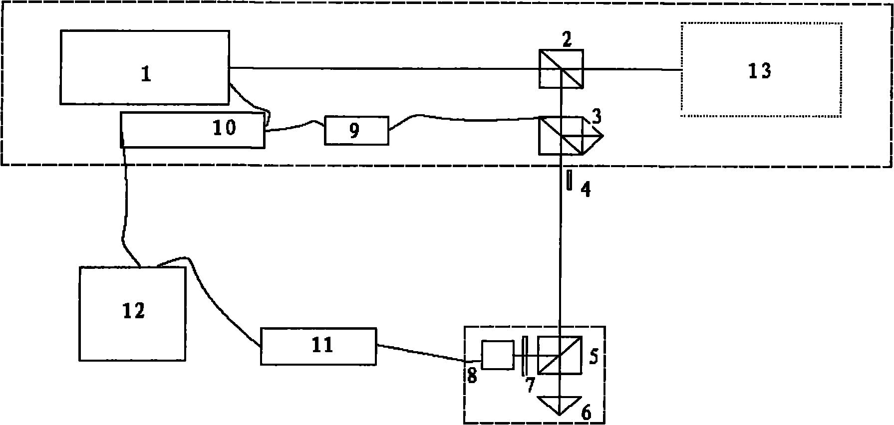
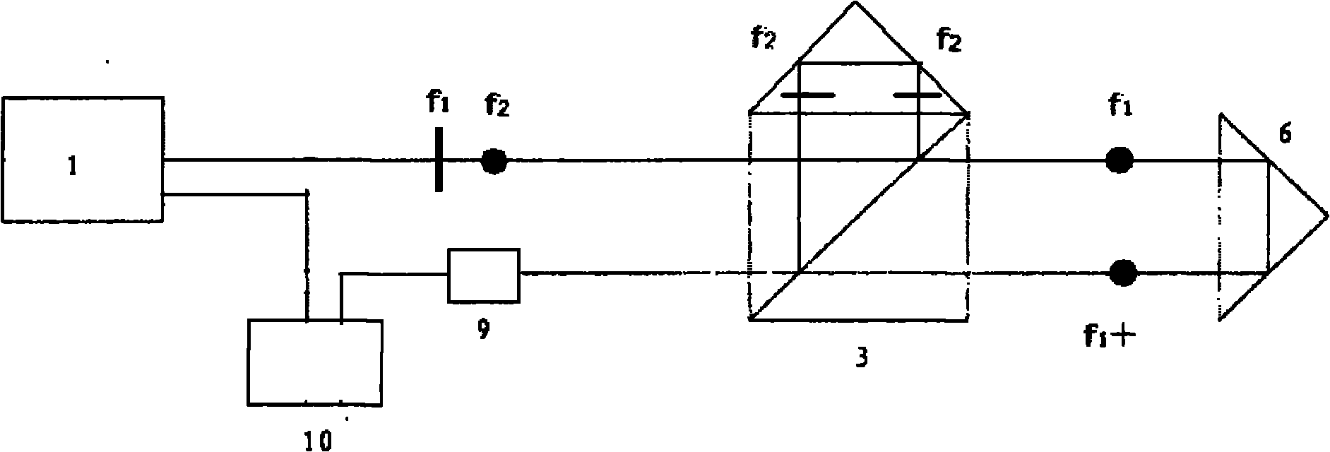
[0038] Such as figure 1 As shown, the device realized by the present invention includes: laser tracker laser 1, beam splitter 2, interference mirror 3, plane reflective rotating mirror 4, beam splitter 5, corner mirror 6, optical filter 7, PSD8, light receiver 9. An interference signal acquisition card 10 , a PSD signal processing module 11 and a microcomputer 12 .

[0039] Such as figure 1 As shown, the interference mirror 3, the plane reflecting rotating mirror 4, the optical receiver 9, and the interference signal acquisition card 10 are installed in the body of the laser tracker to reduce external interference. The beam splitter 5, the corner mirror 6, the optical filter 7, and the PSD 8 are assembled in a housing. The housing is required to be fully enclosed to reduce noise from the environment.

[0040] The incident surface of the beam splitter 2 is placed at an angle of 45° to the laser output from the laser tracker laser 1, and the incident surface of the interferen...


PUM


Abstract

The invention relates to an environment compensation method for measurement employing a laser tracker, which belongs to the technical field of photoclectric engineering and is used for compensation because the laser tracker is easily influenced by environmental factors in the measuring process. The method comprises the following steps of: (1) splitting laser for compensation from the emitted dual-frequency laser of a built-in dual-frequency laser device of the laser tracker; (2) projecting the laser for compensation to a piece to be tested and reflecting with a pyramidal prism to form a compensation light path; (3) additionally arranging an interference component in the compensation light path so that the compensation light path has the dual-frequency laser interference ranging function; (4) additionally arranging a laser splitting element and a PSD (Position-Sensitive Detector) in the compensation light path so that the compensation light path has the PSD displacement measuring function; and (5) compensating a measuring result of the laser tracker in real time by using dual-frequency laser interference ranging data and PSD displacement measuring data. By means of the method disclosed by the invention, the problem of measurement accuracy decrease of the laser tracker which is influenced by environmental factors in the large-size and high-accuracy on-line measurement is solved, and meanwhile, the advantages of simple structure and easiness for implementation are achieved.

Description

technical field [0001] The invention relates to an environment compensation method in the measurement of a laser tracker, which belongs to the technical field of photoelectric engineering and is mainly applied to the environment compensation during the measurement of the laser tracker, in particular to the environment compensation of the large-scale online measurement of the laser tracker. Background technique [0002] In the detection of large-scale and high-precision workpieces, laser trackers have been more and more widely used. However, large-scale measurement is usually on-line measurement, and the influence of the environment (mainly including changes in air refractive index and relative displacement and vibration) has become An important factor that limits the measurement accuracy, and creating laboratory measurement environment conditions in the production workshop will lead to a significant increase in detection costs. Therefore, environmental compensation during the...

Claims


Application Information

Patent Timeline
IPC IPC(8): G01B9/00G01B11/02G01B11/26
Inventor 李杰吴时彬伍凡
Owner INST OF OPTICS & ELECTRONICS - CHINESE ACAD OF SCI
Why Eureka
Try Eureka