Method for measuring diameter of non-contact forging on line by using laser

A non-contact, laser receiving technology, used in measuring devices, optical devices, instruments, etc., can solve the problems of production efficiency and forging quality, increase cold working allowance, poor working conditions, etc., to avoid cold working allowance, The effect of reducing forging allowance loss and simple algorithm

Inactive Publication Date: 2011-04-06
魏青轩
View PDF1 Cites 35 Cited by
  • Summary
  • Abstract
  • Description
  • Claims
  • Application Information

AI Technical Summary

Problems solved by technology

So far, domestic large forging production plants have used simple tools to measure directly with the naked eye at high temperature manually. Not only are the working conditions harsh, but the error is large, so that they have to increase the cold working allowance (up to 60mm), "fat head The phenomenon of "big ears" is common, and the resulting loss of forgings is 15% on average ①
Shaft forgings with a diameter of less than 2m are usually directly measured with a large caliper at a distance less than 1m from the forging. Due to the high temperature, it usually takes a few seconds to complete the measurement. Not only the working conditions are particularly harsh, but the measurement error is quite large ②
This kind of measurement error is also relatively large, the forging must be offline during measurement, and auxiliary positioning is added, the measurement time is long, and it has a great impact on production efficiency and forging quality ②

Method used


Image

  • Method for measuring diameter of non-contact forging on line by using laser
  • Method for measuring diameter of non-contact forging on line by using laser
  • Method for measuring diameter of non-contact forging on line by using laser

Examples


Embodiment

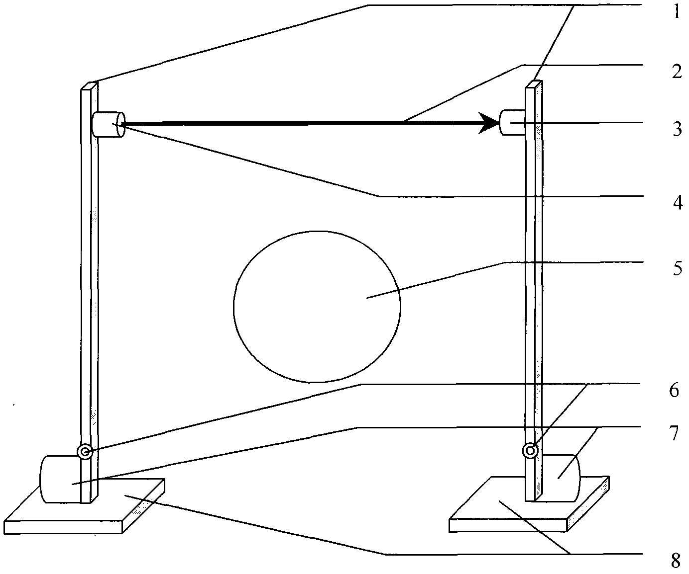
[0020] Example: figure 1 As shown, this embodiment is carried out in the forging plant of Xingtai Machinery Roll Co., Ltd. of Sinosteel Group. The length of the two linear guide rails is 3000mm, and they are installed and fixed on both sides of the forging with a distance of 25 meters. The transmission part that converts the rotary motion of the stepping motor into linear motion adopts the screw transmission mode. The length of the screw is 3000mm. One end of the screw is directly connected to the motor shaft, and the other end is fixed on the guide rail bracket through the bearing support. Installed on the guide rail There is a slider, when the guide rail rotates, the slider moves linearly along the guide rail, the laser emitting device 4 and the laser receiving device 3 are respectively fixed on the sliders of the two lead screws, and the linear guide rail 1 is the laser emitting device and the laser receiving device 3 respectively. The laser receiving device provides a mov...


PUM


Abstract

The invention discloses a method for measuring the diameter of a non-contact forging on line by using laser. A pair of parallel linear guide rails arranged at equal altitude on the two sides of the forging is used in the method. The method is characterized in that: a laser transmitter is arranged on one guide rail, a laser receiver is arranged on the other guide rail, the laser transmitter and the laser receiver are driven to travel by two stepper motors respectively, the positions of the laser transmitter and the laser receiver are kept synchronous during the travel, the distance between the tangent point of the laser and the section circle of the forging can be computed quickly through the travel distance of the stepper motors and the connection and interruption of signals of the laser receiver, so that the diameter size of the forging can be obtained. The method has the advantages that: two mutually independent linear guide rails are adopted, so that the diameter of the forging such as a spindle of a windmill generator and metallurgic rollers in a wider range can be measured by selecting a proper guide rail length; measuring staff are not required to contact high-temperature environment, and manual measurement is avoided, so that the diameter of the current forging can be obtained quickly, precision is high, the shortcomings of long time and large error of the manual operation are overcome, and forging speed and forging precision are improved; the shortcoming of reserving relatively large cold processing allowance according to experience is effectively overcome, the allowance consumption of the forging is reduced, and the energy conservation and consumption reduction are realized.

Description

Technical field: [0001] The invention is mainly used for on-line rapid and accurate measurement of the diameter of the forging when the forging plant of the metallurgical enterprise processes the forging. Background technique: [0002] In the forging plant that needs to forge the diameter of the workpiece, the measurement of the diameter of the forging is an essential step to judge whether the diameter of the forging meets the requirements of the processing technology. So far, domestic large forging production plants have used simple tools to measure directly with the naked eye at high temperature manually. Not only are the working conditions harsh, but the error is large, so that they have to increase the cold working allowance (up to 60mm), "fat head The phenomenon of "big ears" is common, and the resulting loss of forgings is 15% on average ① . Shaft forgings with a diameter of less than 2m are usually directly measured with a large caliper at a distance less than 1m fr...

Claims


Application Information

Patent Timeline
Patent Type & Authority Applications(China)
IPC IPC(8): G01B11/08
Inventor 魏青轩
Owner 魏青轩
Why Eureka
Try Eureka