
Infrared laser perimeter protection method

An infrared laser, perimeter defense technology, applied in the direction of anti-theft alarms, instruments, alarms, etc., can solve the problems of easy to cross, easily affected by the environment, low protection level, etc., to eliminate interference and false alarms, strong protection reliability Effect

Inactive Publication Date: 2011-04-06
THE THIRD RES INST OF MIN OF PUBLIC SECURITY
View PDF8 Cites 21 Cited by
  • Summary
  • Abstract
  • Description
  • Claims
  • Application Information

AI Technical Summary

Problems solved by technology

[0011] In order to overcome the shortcomings and deficiencies of the traditional infrared protection level is not high, easy to cross, easily affected by the environment, etc., the present invention proposes a brand-new infrared laser perimeter protection method, compared with the traditional laser infrared detector, the present invention Using the high-pulse laser ranging technology of pulse time-of-flight measurement, the integrated design of emission and reception, relying on the reflection of the target to identify, the detection has a certain laser emission angle, and adopts the laser radar light wave emission method. When the target breaks in, The laser warning sensor can directly measure and output the position of the intruder, and automatically update the environment, set the target recognition algorithm in the warning area, and calculate the size and speed of the target according to the crossing situation of the target, thereby eliminating various interference false alarms, The two units are combined and installed opposite to each other to output a wide-band beam of light, forming a tight protective light belt, which does not exist in ordinary active lasers.

Method used


Image

  • Infrared laser perimeter protection method
  • Infrared laser perimeter protection method
  • Infrared laser perimeter protection method

Examples


Embodiment Construction

[0040] In order to make the technical means, creative features, goals and effects achieved by the present invention easy to understand, the present invention will be further described below in conjunction with specific illustrations.

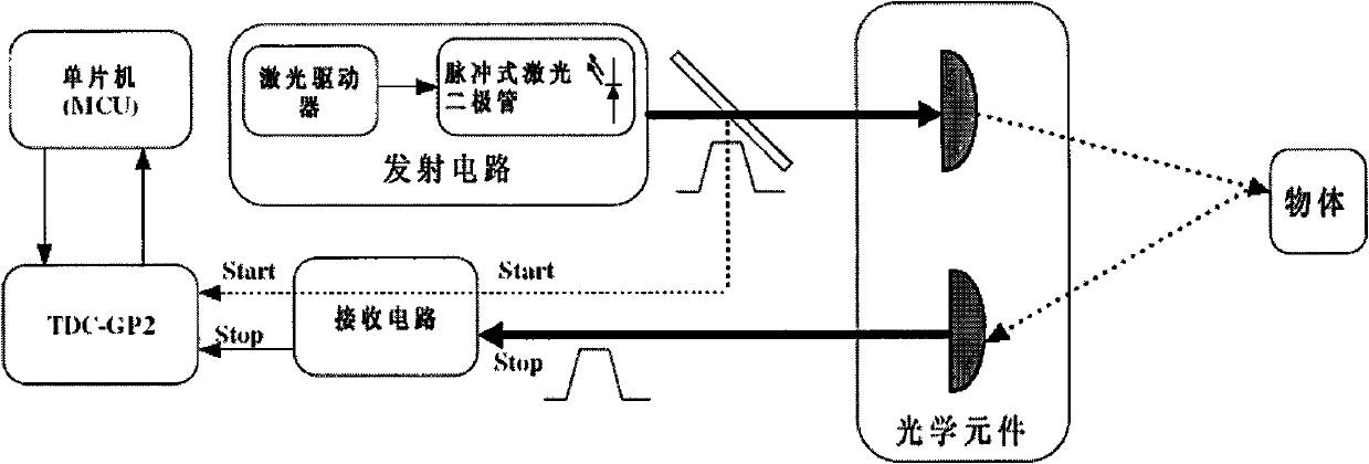
[0041] figure 1 It is the schematic diagram of the front-end laser distance detector. The laser emits ultra-narrow laser pulses with a certain repetition rate. The laser pulses pass through a beam splitter, and one beam of light is received inside the detector to generate a time-of-flight START signal. One beam is collimated and shaped by the transmitting lens and then emitted at a certain angle. When a target breaks in or hits a fixed target, a part of the pulsed light is reflected by the receiving lens and is received by the receiving circuit. After being filtered by the receiving circuit, Denoising, amplification and other processing, and through the pulse front edge detection circuit, finally enter the time measurement module as a STOP signa...


PUM


Abstract

The invention discloses an infrared perimeter protection method for measuring pulsed flight time and distance by using a high laser pulse. In the method, a front end detection system, which adopts infrared laser radar technology, is provided and comprises subsystems such as a laser emission system, a laser receiving system, a data processing and control system, a data transmission system and the like. A detector in the infrared perimeter protection method adopts an emission and receiving integrated design and performs identification by the reflection of an object; the detection has a certain laser emission angle and adopts a light wave emission mode of a laser radar; when the object intrudes, a laser warning sensor can directly measure and output the position of the intruder; an object identification algorithm is set in a warning region; and the size and speed of the object are computed according to the traversing condition of the object; therefore, various interference false alarms are eliminated; and two laser warning sensors are combined and installed in a staggered mode to output a wide band-shaped light beam so as to form a strict protecting light band; therefore, the infrared perimeter protection method has high protection reliability.

Description

Technical field: [0001] The invention relates to a high-pulse laser ranging technology using optical time-of-flight measurement, in particular to an infrared laser perimeter protection method. Background technique: [0002] The application of high technology in the modern anti-terrorist struggle has completely changed many concepts of traditional security precautions, and further caused major changes in the security system. Modern anti-terrorist struggle and security work require that while improving the combat skills of security personnel, they must also discover the location of accidents in advance, so that they can invest in time to stop crimes and suppress the occurrence of threats. [0003] In some important areas, in order to prevent illegal intrusion and various sabotage activities, the traditional preventive measures are to set up some (such as iron fences, walls, wire fence nets, etc.) barriers or barriers at the outer perimeter of these areas, arrange Personnel st...

Claims


Application Information

Patent Timeline
Patent Type & Authority Applications(China)
IPC IPC(8): G08B13/181
Inventor 陈建永李万才沈冬青吴轶轩
Owner THE THIRD RES INST OF MIN OF PUBLIC SECURITY
Learn More