Recognizable mark-based parking position detecting method
A technology for identifying marks and detection methods, applied in the field of parking space detection, can solve problems such as damage to the road surface, unfavorable upgrade or maintenance, loss, etc., and achieve the effect of good technical effect
- Summary
- Abstract
- Description
- Claims
- Application Information
AI Technical Summary
Problems solved by technology
Method used
Image

Examples
Embodiment Construction
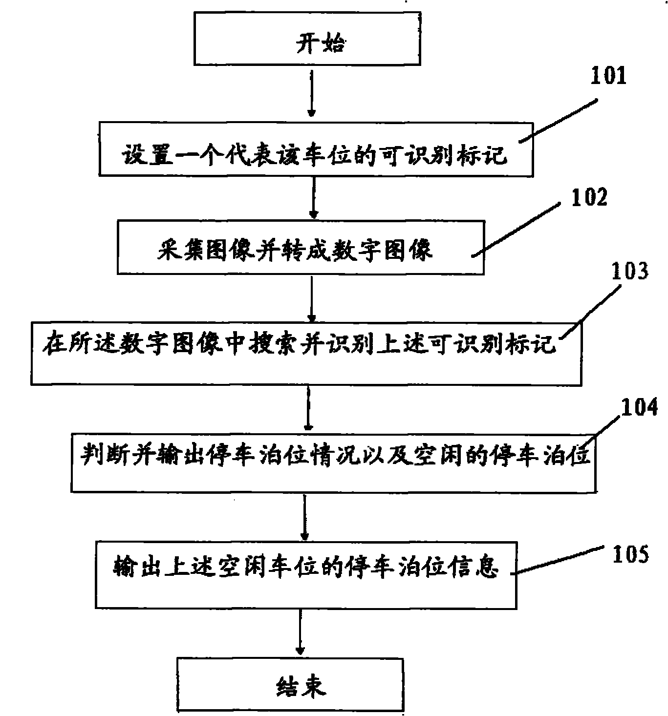
[0029] Below in conjunction with accompanying drawing and embodiment the present invention is described in further detail:
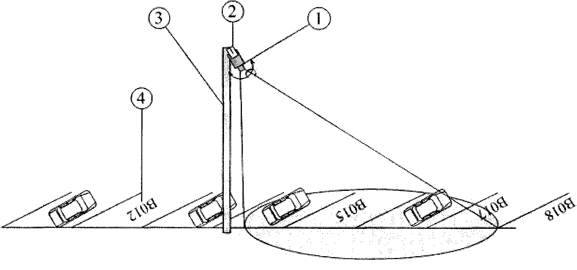
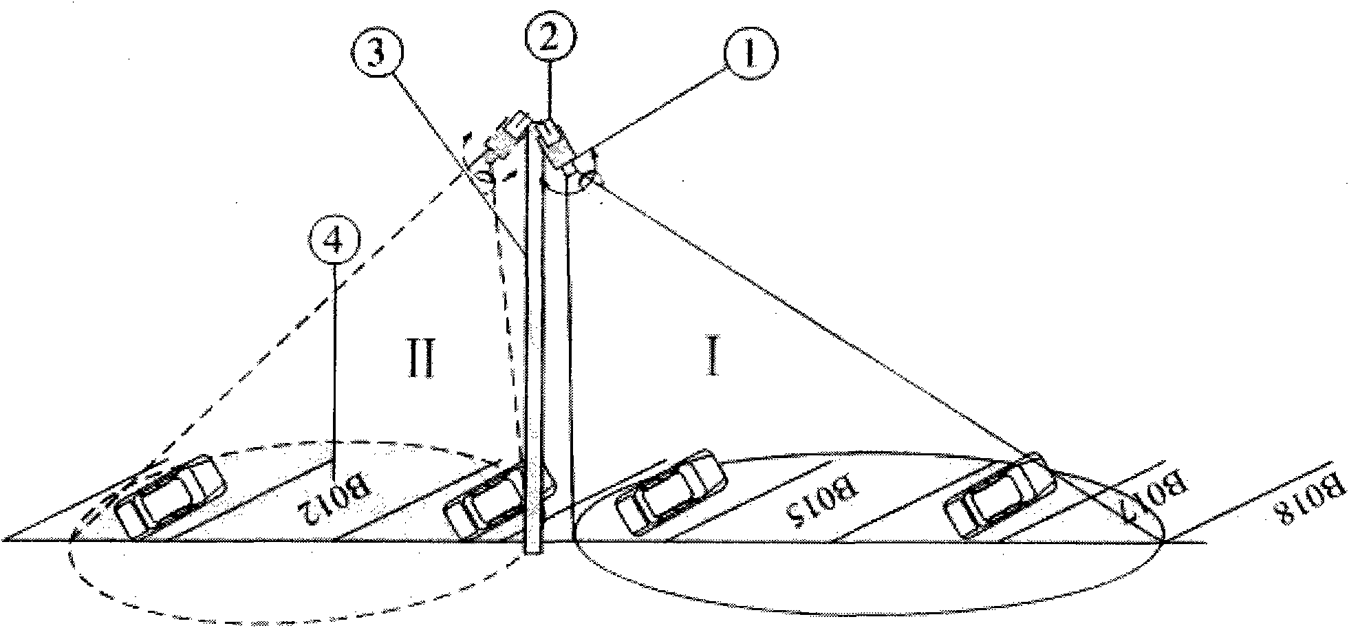
[0030] figure 2 It is a schematic diagram of the image acquisition of the parking berth detection method of the present invention, which mainly performs fixed image acquisition. As shown in the figure, the above-mentioned parking berth detection system based on identifiable marks is set at the parking lot, including image acquisition components, image A processing unit and a display output unit, the image acquisition unit is arranged on the fixed member, and the image acquisition unit is connected with the image processing unit and the display output unit through a wire.
[0031] Since the above-mentioned image acquisition component can collect the image information of the parking spaces in the parking lot, the image information finally enters the image processing component connected to it. After processing, according to the detection results of the rec...
PUM
 Abstract
Description
Claims
Application Information