On-line energy acquisition device of automatic transformation winding based on current transformer (CT)

A technology of automatic conversion and energy acquisition device, which is applied in the direction of conversion equipment that can be converted into DC without intermediate conversion, and can solve the problems such as the insignificant effect of reducing temperature rise, the breakdown of electronic circuit voltage, and the increase of device temperature. Achieve the effect of reducing energy, reducing temperature rise, and enhancing stability

Inactive Publication Date: 2011-04-06
INST OF ELECTRICAL ENG CHINESE ACAD OF SCI
View PDF1 Cites 21 Cited by
  • Summary
  • Abstract
  • Description
  • Claims
  • Application Information

AI Technical Summary

Problems solved by technology

[0005] One of the difficulties in the application of online energy harvesting devices based on CT (current transformers) is that as the bus current increases, too much energy is forcibly injected into the energy harvesting device, causing the temperature of the device to rise sharply
In order to reduce the temperature rise, there are mainly three methods adopted by the existing CT-based energy harvesting devices. One is the method of using the compensation coil, but it is essentially equivalent to transferring heat to the compensation coil, so the eff...

Method used


Image

  • On-line energy acquisition device of automatic transformation winding based on current transformer (CT)
  • On-line energy acquisition device of automatic transformation winding based on current transformer (CT)
  • On-line energy acquisition device of automatic transformation winding based on current transformer (CT)

Examples


Embodiment Construction

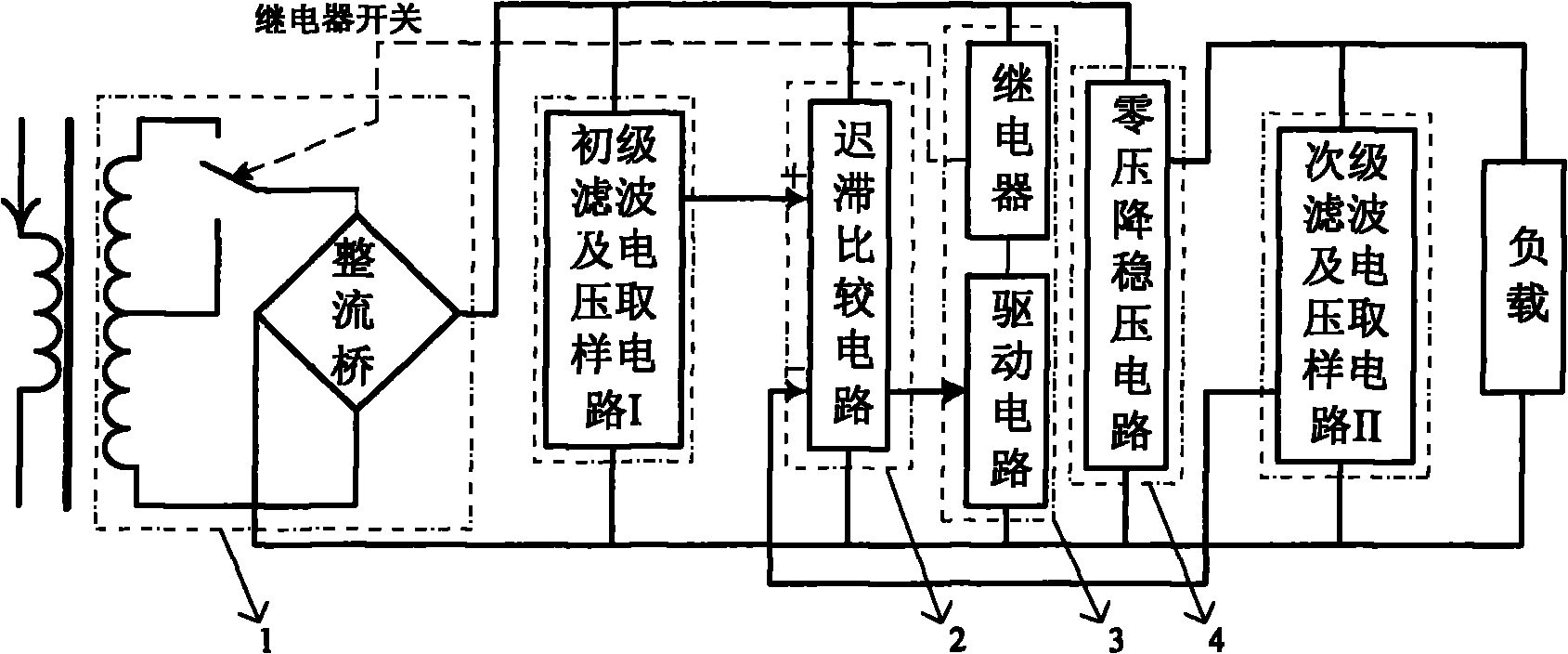
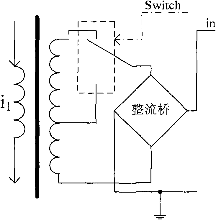
[0029] Such as figure 1 Shown, the present invention comprises small current transformer, energy-taking coil and Schottky rectifier bridge circuit 1, primary filter and voltage sampling circuit 1, hysteresis comparator circuit 3, relay drive control circuit 4, zero-voltage-drop regulator circuit 5, Secondary filtering and voltage sampling circuit II. The small current transformer consists of an energy-taking coil wound on an iron-based nanocrystalline core. The output end of the energy-taking coil is connected to the input end of the Schottky rectifier bridge circuit 1, and the rectified voltage is transferred from the Schottky rectifier bridge circuit 1 The output end of the filter enters the input end of the primary filter and voltage sampling circuit I. The voltage output by the primary filtering and voltage sampling circuit 1 enters the input terminals of the relay drive control circuit 4 and the zero voltage drop voltage stabilizing circuit 5, and the voltage division si...


PUM


Abstract

The invention relates to an on-line energy acquisition device of an automatic transformation winding based on a current transformer (CT). The energy acquisition winding, which winds on the nanocrystal iron core, is utilized to transform magnetic field energy around the alternating current bus into electric energy, and the electric energy is processed by a low voltage drop rectifier circuit (1), a primary filter and voltage sampling circuit I (2), a delay comparison circuit (3), a relay drive control circuit (4), a zero voltage drop voltage regulator circuit (5) and a secondary voltage sampling and filter circuit II (6) to obtain a stable output voltage. The device of the invention can be used for transforming the magnetic field energy around the alternating current bus into the electric energy through the coupling of the magnetic circuit so as to provide stable electric energy for the state monitoring sensor nodes of the power grid line and the electrical equipment. The device of the invention is especially suitable to be used as a power supply for wireless sensor monitoring nodes of current, voltage, temperature and the like for high voltage pylon wires in remote districts, such as mountains, lake and the like.

Description

technical field [0001] The invention relates to a suspension power-taking device for a high-voltage line, in particular to a device for converting stray magnetic field energy around an AC bus bar into stable electric energy by using a small CT. Background technique [0002] In order to improve energy utilization efficiency and apply renewable energy access, the current power grid is gradually developing towards a flexible smart grid characterized by intelligent control, management and analysis, which requires various sensors to monitor the current of grid lines, Real-time monitoring of parameters such as voltage, temperature and power equipment operation. [0003] However, while we enjoy the convenience brought by electronic technology, another problem arises, that is, how to provide stable energy for these sensing devices. At present, various sensing devices used for power grid status monitoring are mostly powered by green energy (such as solar energy, wind energy, etc.) a...

Claims


Application Information

Patent Timeline
IPC IPC(8): H02M5/12
Inventor 辛守乔肖立业戴少涛张国民邱清泉翟家星刘怡
Owner INST OF ELECTRICAL ENG CHINESE ACAD OF SCI
Why Eureka
Try Eureka