Method for making magnetic components with m-phase coupling, and related inductor structures

A technology of coupled inductance and leakage inductance, applied in the direction of inductors, electrical components, fixed inductors, etc., can solve the problem of large leakage inductance

Active Publication Date: 2011-04-06
VOLTERRA SEMICONDUCTOR
View PDF1 Cites 11 Cited by
  • Summary
  • Abstract
  • Description
  • Claims
  • Application Information

AI Technical Summary

Problems solved by technology

A large window width 510 is required to provide a flux le

Method used


Image

  • Method for making magnetic components with m-phase coupling, and related inductor structures
  • Method for making magnetic components with m-phase coupling, and related inductor structures
  • Method for making magnetic components with m-phase coupling, and related inductor structures

Examples


Embodiment Construction

[0037] It should be noted that, for clarity of view, some elements in the figures are not shown to scale. A specific example of a component is indicated by using a label in parentheses (eg, winding 861(1)), and a label without parentheses indicates any such component (eg, winding 816).

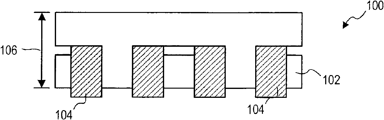
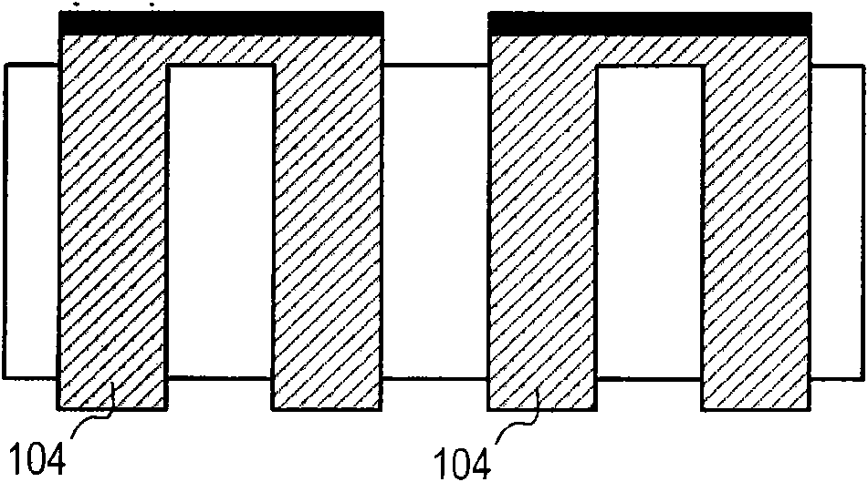
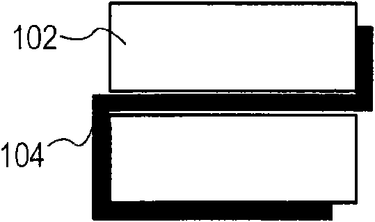
[0038] Figure 8 A top perspective view of an M-phase coupled inductor 800 is shown, Figure 9 A top plan view of the M-phase coupled inductor 800 is shown. Figure 9 Windings 816 are not shown to more clearly illustrate core 802 . but, Figure 10 A top plan view of coupled inductor 800 including winding 816 is shown. exist Figure 10The edges of the winding 816 that cannot be seen in the top plan view are shown in dashed lines. Figure 11 shows the coupled inductor 800 along the Figure 10 Cross-sectional view of line B-B. Such as Figure 11 As shown, coupled inductor 800 has height 1108 . Although Figures 8 to 11 M is equal to 3 in the illustrated example of coupled inductor 800 ...


PUM


Abstract

An M-phase coupled inductor including a magnetic core and M windings, where M is an integer greater than one. The magnetic core is formed of a core material, and the magnetic core includes a first outer leg forming a first gap. The first gap includes a first gap material having lower magnetic permeability than the core material. Each winding is wound at least partially around at least a portion of the magnetic core, and each winding has a respective leakage inductance. The first gap causes the leakage inductances to be greater than if the first outer leg did not form the first gap. The coupled inductor may be used in a power supply, and the power supply may be used in a computing apparatus.

Description

[0001] Cross References to Related Applications [0002] This application claims priority to U.S. Provisional Patent Application No. 61 / 036,836, filed March 14, 2008, and U.S. Provisional Patent Application No. 61 / 046,736, filed April 21, 2008, the contents of which Both are incorporated herein by reference. Background technique [0003] US Patent No. 6,362,986 to Schultz et al. (Schultz '986) describes a DC-DC converter with a multiphase coupled inductor topology, the disclosure of which is incorporated herein by reference. Advantages of such a converter include reduced ripple current in the inductor and switcher, which can reduce the inductance per phase, or reduce the switching frequency of the converter with conventional multiphase DC-DC converter topologies. Therefore, a DC-DC converter with a magnetically coupled output inductor has excellent transient response without loss of efficiency compared to conventional multiphase topologies. This results in a significant redu...

Claims


Application Information

Patent Timeline
IPC IPC(8): H01F37/00
CPCH02M7/003H01F3/14H01F2038/026H01F38/023G05F1/38G05F1/32G05F1/325G05F1/33H02M3/1584H01F27/24H02M3/158
Inventor 亚历山德·伊克拉纳科夫安东尼·斯特拉塔科夫
Owner VOLTERRA SEMICONDUCTOR
Why Eureka
Try Eureka