A soft switching conversion device based on a flyback converter

A flyback converter and conversion device technology, which is applied to output power conversion devices, DC power input to DC power output, instruments, etc., can solve the problem that high efficiency cannot be guaranteed, it is difficult to effectively improve the power density of the adapter system, and the overall Converter efficiency and other issues

Active Publication Date: 2018-04-10
ZHEJIANG UNIV
View PDF5 Cites 33 Cited by
  • Summary
  • Abstract
  • Description
  • Claims
  • Application Information

AI Technical Summary

Problems solved by technology

[0004] However, this existing technology has a series of insurmountable shortcomings in increasing the switching frequency: ① this technology uses a passive RCD network (such as figure 1 shown) to consume the energy in the leakage inductance of the Flyback circuit to suppress the peak of the drain terminal voltage of the primary side power tube. The RCD snubber circuit consumes the energy in the leakage inductance every cycle to clamp the drain terminal voltage at the highest level
When the converter works at a lower frequency (80kHz~180kHz), the energy loss is not very large, but when the converter works at a high frequency (>1MHz) in order to reduce the volume, the loss of the RCD clamp circuit will be greatly increased reduce the efficiency of the overall converter
②Not only that, since the RCD circuit only clamps the highest point of the MOS tube drain terminal voltage V clamp , the whole circuit will still oscillate at high frequency when the MOS tube is turned off; if the converter operates at high frequency, this high-frequency oscillation will evolve into an electromagnetic interference (EMI) problem with the increase of switching times at the same time
③Although quasi-resonant valley conduction Flyback achieves smaller primary-side switching loss than traditional ones, this conduction loss will still become an unacceptable loss ratio for the system at high frequencies
From the above, the current mainstream quasi-resonant valley conduction Flyback solution cannot guarantee high efficiency and make the converter work at high frequencies, and it is difficult to effectively improve the power density of the entire adapter system

Method used


Image

  • A soft switching conversion device based on a flyback converter
  • A soft switching conversion device based on a flyback converter
  • A soft switching conversion device based on a flyback converter

Examples


Embodiment Construction

[0034] In order to describe the present invention more specifically, the technical solutions of the present invention will be described in detail below in conjunction with the accompanying drawings and specific embodiments.

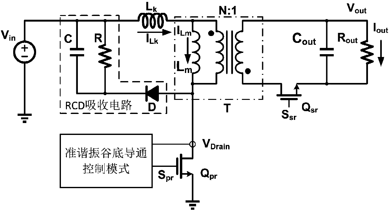
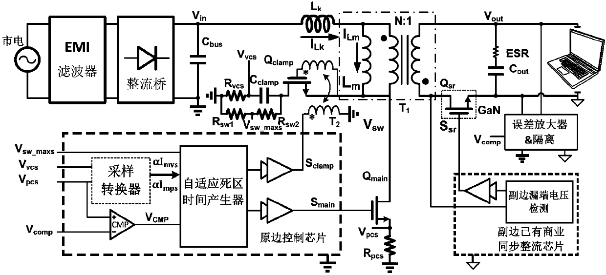
[0035] Such as Figure 6 As shown, the present invention is based on the power topology of the soft switching device of the flyback converter, compared with the traditional Flyabck power topology: the present invention is in the main power tube Q main A clamping branch to a fixed potential is connected between the transformer T and the Figure 6 , the fixed potential is V in . The clamping branch consists of clamping tube Q clamp with clamp capacitor C clamp Composition, where the switching signal S of the clamp tube clamp and main power tube switching signal S main Complementary, and leave a certain controllable dead time for each other.

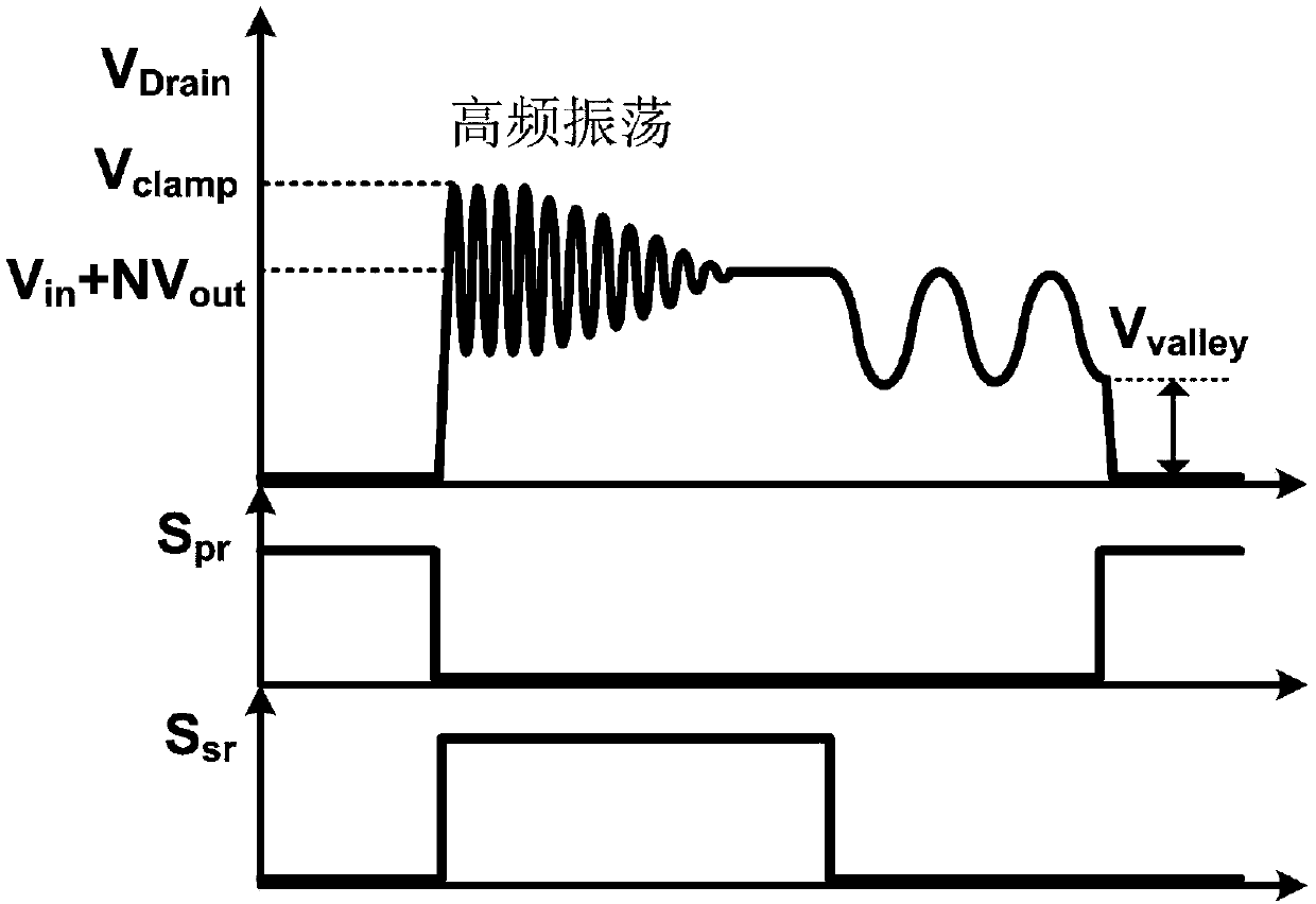
[0036] The waveforms of each key part of the soft switching power topology are as follows Figure 7 As shown...


PUM


Abstract

The invention provides a soft switching conversion device based on a flyback converter. On the basis of the conventional Flyback converter power topology, a clamp branch consisting of a controllable power clamper tube and a clamp capacitor is connected to a drain end of a main power tube in series; a primary side chip of the conversion device receives information such as the peak excitation current, the valley bottom excitation current and the maximum voltage of switching nodes of a converter power loop and generates ideal drive dead time varying with an input voltage and a load condition to control the main power tube and the clamper tube, so that the voltage oscillation of the drain end of the power tube caused by leakage inductance can be completely eliminated. Owing to the basically loss-free soft switching technology of the MOS tube active clamp, the stable clamp voltage value and the primary-side and auxiliary-side full working conditions, the device can work at a high frequency(> 1MHz) and can greatly increase the power density of a power adapter when being applied to the adapter.

Description

technical field [0001] The invention belongs to the technical field of switching power supply control, and in particular relates to a soft switching conversion device based on a flyback converter. The device can be applied to AC-DC power adapters such as mobile phones, notebook computers, tablet computers and ultra-thin household TV sets. Background technique [0002] With the increasing miniaturization requirements of consumer electronics AC-DC power adapters, especially notebook computer adapters, coupled with the improvement of the output energy standard of adapters by fast charging standards, it is necessary to improve the power density of AC-DC power adapters. Switching power supply technology issues to be resolved. Under the current technical conditions, since almost all AC-DC power adapters are switching power supplies, increasing the switching operating frequency can reduce the volume of passive power devices and filters in the switching power supply. In addition, t...

Claims


Application Information

Patent Timeline
Patent Type & Authority Applications(China)
IPC IPC(8): H02M3/335H02M1/08
CPCH02M1/083H02M3/33592H02M1/0058Y02B70/10
Inventor 唐圣鹏奚剑雄何乐年
Owner ZHEJIANG UNIV
Why Eureka
Try Eureka