Electrolytic capacitor-free LED driving power supply based on flyback converter leakage inductance energy utilization

A flyback converter and LED driving technology, which is applied in DC/DC converters, power electronics, and AC/DC fields, can solve the problems of affecting the overall life of LED lighting, low overall efficiency, and low integration, and achieve leakage Sensitive energy utilization, small size and high reliability

Inactive Publication Date: 2014-09-03
SHANGHAI UNIV
View PDF4 Cites 34 Cited by
  • Summary
  • Abstract
  • Description
  • Claims
  • Application Information

AI Technical Summary

Problems solved by technology

[0006] The purpose of the present invention is to overcome the shortcomings of the LED drive power supply affecting the overall life of LED lighting due to the use of electrolytic capacitors in AC power supply applications, and to overcome the shortcomings of the traditional two-stage topology LED drive power supply such as low efficiency, many components, large volume, and low integration. , providing a non-electrolytic capacitor LED drive power supply based on the utilization of the leakage inductance energy of the flyback converter

Method used


Image

  • Electrolytic capacitor-free LED driving power supply based on flyback converter leakage inductance energy utilization
  • Electrolytic capacitor-free LED driving power supply based on flyback converter leakage inductance energy utilization
  • Electrolytic capacitor-free LED driving power supply based on flyback converter leakage inductance energy utilization

Examples


Embodiment 1

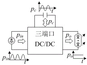
[0025] Embodiment one: if image 3 As shown, a structural block diagram of an electrolytic capacitor LED drive power supply based on the utilization of the leakage inductance energy of the flyback converter. The main circuit is a three-port DC / DC converter, and the energy storage capacitor in the main circuit can balance the instantaneous input power under different input power conditions through the auxiliary circuit p in and output power p o The low-frequency pulsating power realizes constant output power regulation and provides constant drive current for LED loads.

Embodiment 2

[0026] Embodiment two: if Figure 4 As shown, a main circuit of an electrolytic capacitor LED drive power supply based on the utilization of leakage inductance energy of a flyback converter, including: a bridge rectifier circuit (1), an auxiliary circuit (2), a main switch tube (3), and a flyback transformer (4), rectification circuit (5), output filter capacitor (6) and LED load (7). It is characterized in that: the bridge rectifier circuit (1) is sequentially connected with the auxiliary circuit (2), the main switching tube (3), the flyback transformer (4), the rectifier circuit (5), the output filter capacitor (6) and the LED load (7).

Embodiment 3

[0027] Embodiment 3: This embodiment is basically the same as Embodiment 2, and its special features are as follows: the bridge rectifier circuit (1) is composed of a first diode ( D r1 ), the second diode ( D r2 ), the third diode ( D r3 ) and the fourth diode ( D r4 ) composition; the first diode ( D r1 ) is connected to the anode of the third diode ( D r3 ), the cathode of the second diode ( D r2 ) to the anode of the fourth diode ( D r4 ), the cathode of the first diode ( D r1 ) cathode and the second diode ( D r2 ), the cathode of the third diode ( D r3 ) anode and the fourth diode ( D r4 ) of the anode docking; the auxiliary circuit (2) consists of an energy storage capacitor ( C a ), the second switching tube ( S 2 ), the fifth diode ( D a1 ), the sixth diode ( D a2 ) composition; the energy storage capacitor ( C a ) positive terminal and the second switch tube ( S 2 ) connected to the drain, the second switch tube ( S 2 ) source and th...


PUM


Abstract

The invention discloses an electrolytic capacitor-free LED driving power supply based on flyback converter leakage inductance energy utilization. The power supply comprises an alternative current input power supply, a bridge rectifier circuit, an auxiliary circuit, a main switch tube, a flyback transformer, a rectifier circuit, an output filter capacitor and an LED load. The power supply has the characteristics and advantages that firstly, as energy storage capacitance voltage of the auxiliary circuit is designed into a working mode that direct current voltage is overlapped with large pulse ripple voltage, not only is the dependence of the LED driving power supply on an electrolytic capacitor eliminated, but also flyback converter leakage inductance energy utilization is achieved; secondly, the flyback transformer works in a current interrupted mode, and input power factor correction is achieved; thirdly, due to adoption of the auxiliary circuit, the low frequency pulse power of input power pin and output power po can be balanced, and the constant current can be achieved to drive the LED load through coordination work of the auxiliary circuit and a main circuit.

Description

technical field [0001] The present invention relates to the field of power electronics technology, in particular to a non-electrolytic capacitor LED drive power supply based on the utilization of leakage inductance energy of a flyback converter, which belongs to AC / DC (AC / DC) and DC / DC (DC / DC) converters field. Background technique [0002] With the continuous progress of key technologies of light-emitting diodes (LEDs), LED lighting has become a new generation of ideal lighting sources to replace traditional lighting (such as incandescent lamps, etc.). LED lighting can not only improve lighting quality, but also reduce lighting power consumption. It has the advantages of energy saving, environmental protection, high luminous efficiency, long life, and easy dimming. The LED lighting source mainly includes two parts: the driving power supply and the LED light-emitting chip. In the case of AC power supply, in order to meet the harmonic requirements of IEC61000-3-2, the LED d...

Claims


Application Information

Patent Timeline
Patent Type & Authority Applications(China)
IPC IPC(8): H02M3/335H05B37/02
Inventor 汪飞钟元旭
Owner SHANGHAI UNIV
Why Eureka
Try Eureka