Eureka AIR delivers breakthrough ideas for toughest innovation challenges, trusted by R&D personnel around the world.

Laser cleaning equipment and method for sol-gel membrane surface

A technology for cleaning equipment and gel films, applied in cleaning methods and appliances, chemical instruments and methods, etc., can solve problems such as physical injury of operators, damage of components with low threshold value, degradation of optical beam quality, etc., to achieve obvious cleaning effect and process Controllable and reproducible results

Inactive Publication Date: 2011-04-13
UNIV OF ELECTRONICS SCI & TECH OF CHINA
View PDF4 Cites 12 Cited by
  • Summary
  • Abstract
  • Description
  • Claims
  • Application Information

AI Technical Summary

Problems solved by technology

Therefore, the pollution of quartz dust particles on the membrane surface will be unavoidable. On the one hand, the existence of these particles will cause the beam quality of the subsequent optical path to decrease due to effects such as scattering and reflection; on the other hand, it will cause low threshold damage to components.
[0003] Traditional cleaning techniques include mechanical cleaning, chemical wet cleaning, ultrasonic cleaning, etc., which are often powerless to clean micron and submicron pollutants
In addition, the method of mechanical wiping is likely to cause scratches on the membrane surface; organic spraying, showering, soaking, etc. are likely to cause peeling off of the membrane surface or secondary pollution, and are likely to cause harm to the operator's body; ultrasonic cleaning will Potential damage to both film and component

Method used


Image

  • Laser cleaning equipment and method for sol-gel membrane surface
  • Laser cleaning equipment and method for sol-gel membrane surface
  • Laser cleaning equipment and method for sol-gel membrane surface

Examples


Embodiment Construction

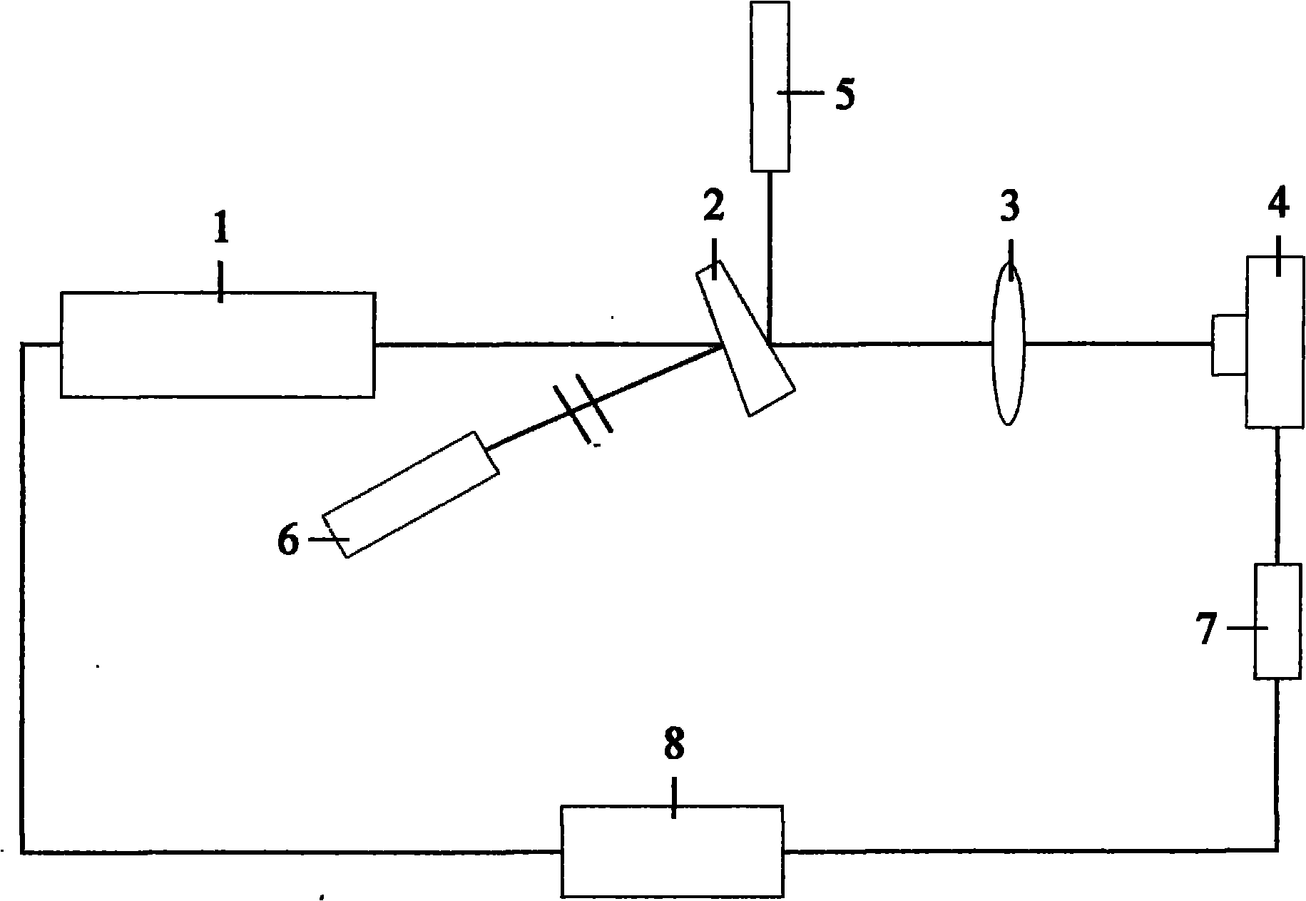
[0022] Such as figure 1 As shown, the sol-gel film surface laser cleaning equipment includes a pulsed laser 1, a splitting plate 2, a lens 3, a two-dimensional mobile platform 4, a collimated laser 5, an energy meter 6, a stepping motor 7 and a computer 8; On the two-dimensional mobile platform 4, the computer 8 is respectively connected with the pulse laser 1 and the stepping motor 7 through cables, and the computer controls the pulse laser 1 and the stepping motor 7, and the stepping motor 7 controls the two-dimensional mobile platform 4; the pulse laser 1 excites The focused high-energy pulse laser is sufficient to induce air optical breakdown. The pulse laser can be Nd:YAG (Nd-doped yttrium aluminum garnet) laser, XeF (xenon fluoride) excimer laser, etc., which are controlled by computer 8 through cables; The pulsed laser light emitted by the pulsed laser 1 is divided into two beams after splitting the plate 2. One beam enters the energy meter 6 and is called probe light; ...


PUM


Abstract

The invention relates to laser cleaning equipment and a laser cleaning method for a sol-gel membrane surface and belongs to the technical field of optical materials and laser. The cleaning equipment comprises a pulse laser, a chopping board, a lens, a two-dimensional movement platform, a collimation laser, an energy meter, a stepping motor and a computer; a sample is arranged at the two-dimensional movement platform with micron resolution, the computer is connected with the pulse laser and the stepping motor respectively through a cable and controls the pulse laser and the stepping motor, and the stepping motor controls the two-dimensional movement platform; pulse laser emitted by the pulse laser is divided into two beams, namely probe light and main laser after passing through the chapping board; the probe light enters the energy meter; and the main laser reaches the two-dimensional movement platform after being focused through the lens; and collimation light generated by the collimation laser reaches the chopping board and is superposed with the main laser, and the position of the main laser is judged through the collimation light. The equipment has the advantages of avoiding secondary pollution, prolonging service life of coating film elements, not leaving a dead angle and damaging the membrane surface, along with high cleaning efficiency and the like.

Description

technical field [0001] The invention relates to a laser cleaning device and a cleaning method thereof, belonging to the technical field of optical materials and lasers, in particular to a laser cleaning device and a cleaning method of a sol-gel film surface. Background technique [0002] In large high-power laser systems, quartz materials (main components: SiO 2 ) are widely used in lenses, windows and shielding sheets, etc. During the operation of strong lasers, the splashing of quartz particles caused by damage to certain components can easily contaminate other undamaged components. Sol-gel chemical films (such as SiO 2 Single-layer anti-reflection coating, etc.) are widely used in high-power laser systems due to their low cost, excellent anti-laser damage performance, simple coating process, and suitable for coating large-diameter components. However, the chemical membrane has a loose and porous structure, and the nanoscale pores are covered with abundant dangling bonds...

Claims


Application Information

Patent Timeline
Patent Type & Authority Applications(China)
IPC IPC(8): B08B7/00
Inventor 王治国
Owner UNIV OF ELECTRONICS SCI & TECH OF CHINA
Why Eureka
Eureka Blog
Learn More