Automatic gearshift device of electric vehicle

A technology of electric vehicles and electric motors, applied in the direction of electromechanical devices, electric vehicles, electric components, etc., can solve the problems of energy waste of batteries, large impact of batteries and controllers, small range of motor torque changes, etc., to achieve a high degree of automation, The effect of expanding the applicable area and facilitating high-speed operation

Active Publication Date: 2011-04-13
YADEA TECH GRP CO LTD
View PDF3 Cites 6 Cited by
  • Summary
  • Abstract
  • Description
  • Claims
  • Application Information

AI Technical Summary

Problems solved by technology

[0002] The driving power of the electric vehicle comes from the electric motor, but the range of torque of the electric motor is small, and the traction force and speed cannot adapt to the changing requirements of various complex resistance ranges.
At present, the speed of electric vehicles is adjusted only by adjusting the duty cycle (pwm). The duty cycle is the ratio of the cycle time occupied by the high level to the entire cycle time. When starting, accelerating or climbing a slope, the driving wheels are very easy to slip excessively, resulting in poor driving performance, handling performance and stability of the vehicle; the moment of starting is maintained by a large current, which has a large impact on the battery and controller, and downhill and coasting The medium back electromotive force has a great impact on the controller and the motor itself, and the controller and the motor are easy to burn out during climbing and long downhill; it cannot meet the requirements of complex road conditions, and it is necessary to frequently turn the handle and brake, resulting in a large waste of battery energy , which shortens the mileage of the electric vehicle; at the same time, the impact on the controller MOS tube is too large
Therefore, at present, the speed is adjusted only by the duty cycle, which restricts the application in mountains and hills, and shortens the service life of the battery, controller, and motor.

Method used


Image

  • Automatic gearshift device of electric vehicle
  • Automatic gearshift device of electric vehicle
  • Automatic gearshift device of electric vehicle

Examples


Embodiment Construction

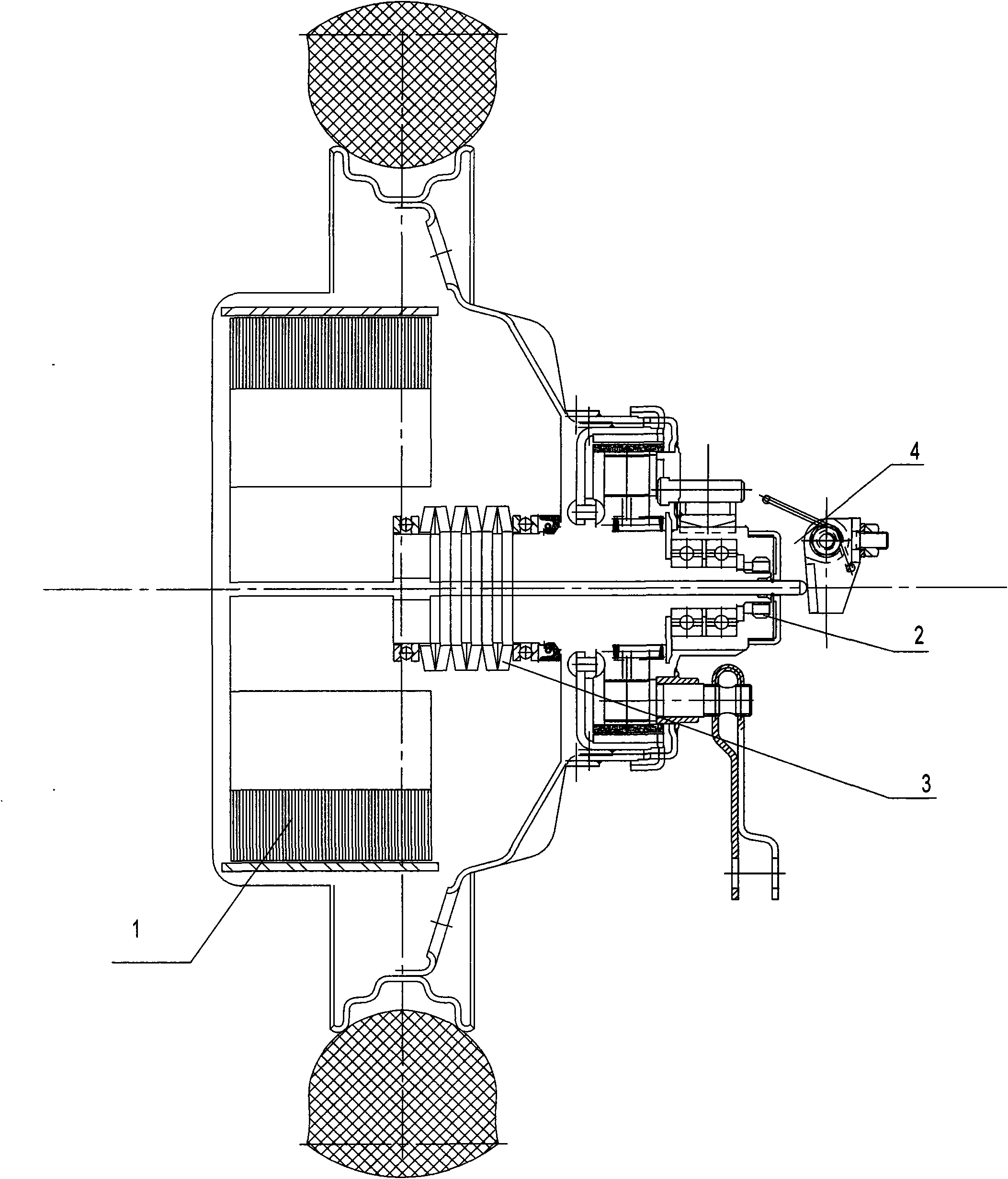
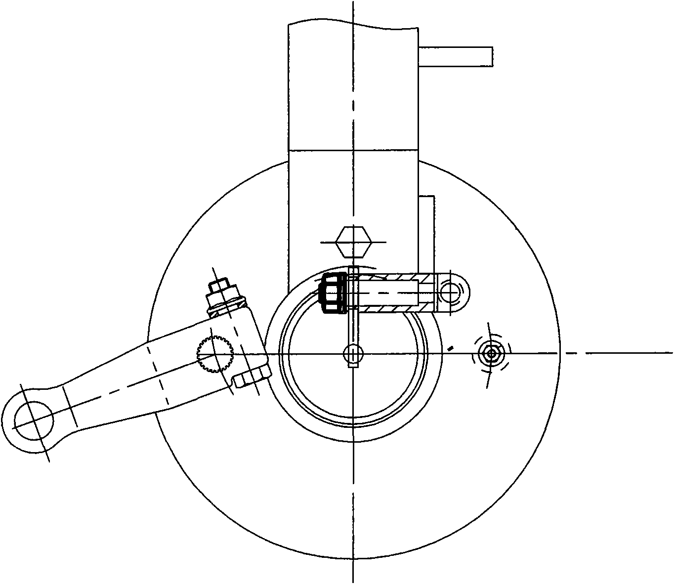
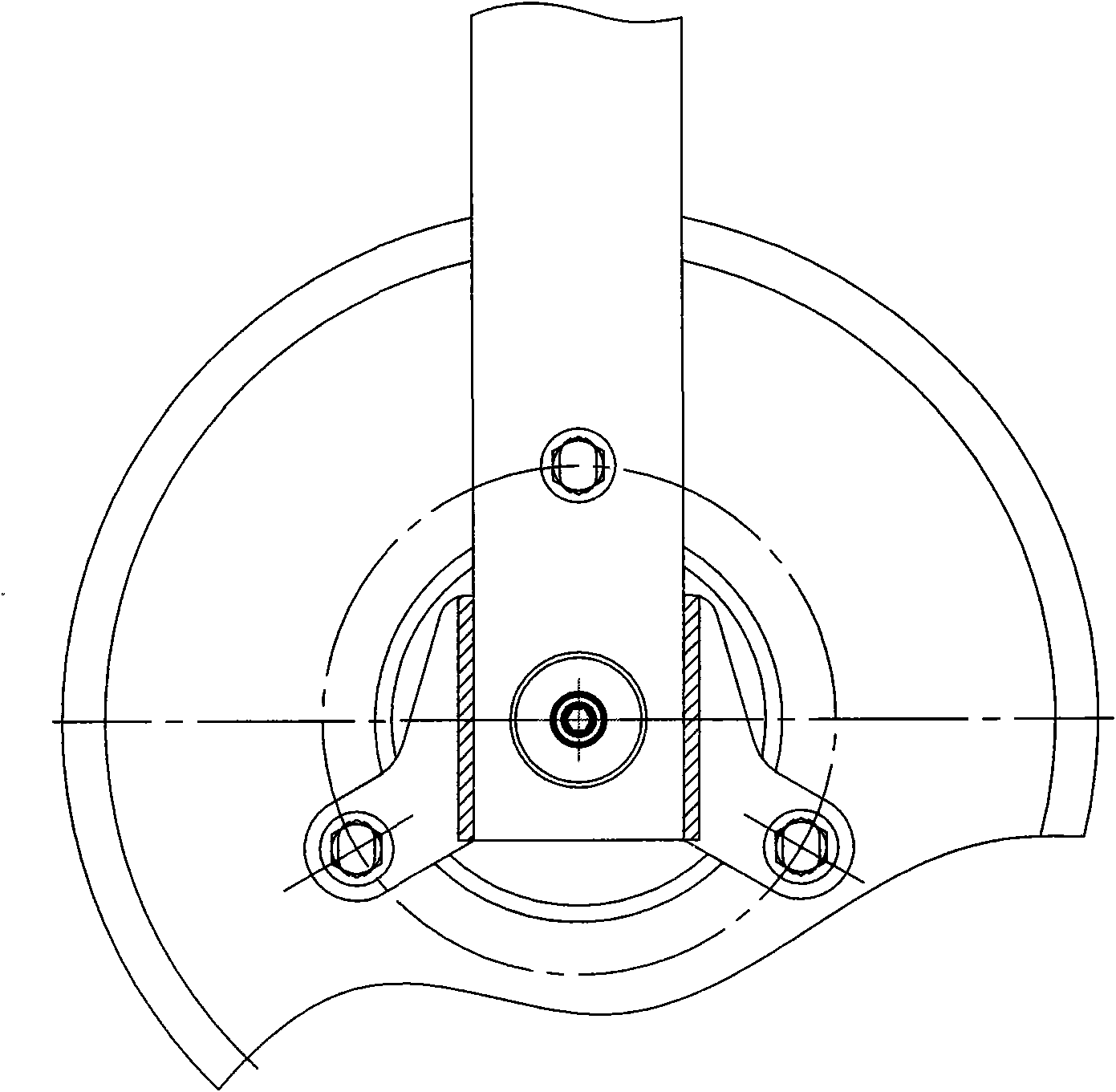
[0024] Below is that the present invention will further describe embodiment in conjunction with accompanying drawing:

[0025] Figure 1 ~ Figure 3 As shown, the present invention is composed of a motor 1, a tower transmission gear 2, a disc spring 7, an adaptive disc spring cam differential transmission sensing mechanism 3, an adaptive cam speed change mechanism 4, a wheel hub 5 and a tire 6, etc. to form an electric vehicle transmission transmission. Sensitive automatic transmission shift drive. The motor adopts a brushless self-adaptive motor, and a closed-loop system is realized through the motor 1, the tower transmission gear 2, the self-adaptive dish spring cam differential transmission sensor mechanism 3, and the self-adaptive cam speed change mechanism 4. (HALL is S41F, magnetic steel 35H, enameled wire QZ130 / 2) First, the Hall handle gives the motor 1 a signal to energize and rotate to drive the tower transmission gear 2 to rotate, and the tower transmission gear 2 d...


PUM


Abstract

The invention discloses an automatic gearshift device of an electric vehicle and relates to the field of vehicle-speed control components. The present electric vehicle is controlled by a Hall rotating handle opening ring, cannot realize the automatic conversion of the road condition and the torsion, restricts the application in mountainous and hilly regions and starts heavy current so as to shorten the service life of a storage battery, an electric motor, a controller and other important components., therefore, according to the technical scheme provided by the invention, the automatic gearshift device comprises a tower type transmission gear which is rotatably connected with the electric motor; the tower type driving gear is rotatably connected with a disc spring cam differential drive sensor which is connected with a cam transmission ECU (Electronic Control Unit) controller; and the ECU controller is connected with an electrical signal of the electric motor to form closed loop control. The invention has the advantages of strong climbing capability, long trip mileage, high automatic degree, quick response, energy saving and long service life.

Description

technical field [0001] The invention relates to the field of vehicle speed control components, in particular to an automatic shifting device for an electric vehicle. Background technique [0002] The driving power of the electric vehicle comes from the electric motor, but the range of torque of the electric motor is small, and the traction force and speed cannot adapt to the changing requirements of various complex resistance ranges. At present, the speed of electric vehicles is adjusted only by adjusting the duty cycle (pwm). The duty cycle is the ratio of the cycle time occupied by the high level to the entire cycle time. When starting, accelerating or climbing a slope, the driving wheels are very easy to slip excessively, resulting in poor driving performance, handling performance and stability of the vehicle; the moment of starting is maintained by a large current, which has a large impact on the battery and controller, and downhill and coasting The medium back electrom...

Claims


Application Information

Patent Timeline
Patent Type & Authority Applications(China)
IPC IPC(8): B60L15/20H02K7/116
CPCY02T10/641Y02T10/64Y02T10/72
Inventor 董经贵
Owner YADEA TECH GRP CO LTD
Why Eureka
Try Eureka