Vacuum evaporation system capable of controlling evaporating airflow distribution and components

A technology of vacuum evaporation and air flow, which is applied in the direction of vacuum evaporation plating, ion implantation plating, metal material coating technology, etc., can solve the problems of complex structure control factors, waste of evaporation material process cost, long debugging process, etc. To achieve the uniformity of evaporation, shorten the distance of evaporation, and reduce the volume

Active Publication Date: 2011-04-13
SHANGHAI UNIV
View PDF6 Cites 26 Cited by
  • Summary
  • Abstract
  • Description
  • Claims
  • Application Information

AI Technical Summary

Problems solved by technology

However, its structure is complicated. There are many factors to control the uniform evaporation rate on the line, and the equipment cost is relatively high.
In addition, since the general organic light-emitting layer often requires dopants, multi-source evaporation is required.
This not only brings more control, but also requires a long debugging process to adjust its stable evaporation rate, which also brings a lot of waste of evaporation material and process cost

Method used


Image

  • Vacuum evaporation system capable of controlling evaporating airflow distribution and components
  • Vacuum evaporation system capable of controlling evaporating airflow distribution and components
  • Vacuum evaporation system capable of controlling evaporating airflow distribution and components

Examples


Embodiment 1

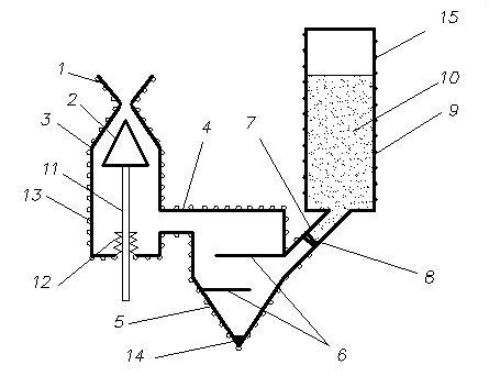
[0027] Example 1: see figure 1, the vacuum evaporation system that can control the distribution and composition of the evaporation airflow is composed of an evaporation gun (3), a high-temperature pipeline (4), a high-temperature evaporation crucible (5), a feeding valve (8) and a storage tank (9). The evaporation gun (3) has a spout (1) with upper and lower conical surfaces, and a movable airflow guide plug (2) is placed inside the spout (1), and is placed in front of the spout (1) to be evaporated. The substrate (16), the evaporation gun (3) is connected with the high-temperature evaporation crucible (5) with a cross baffle (6) through the heating pipe (4) or buffer bottle, and the other side of the crucible (5) passes The pipeline (7) equipped with the feeding valve (8) is connected to the storage tank (9). There are heating coils (13) on the outer wall of the evaporation gun (3), the heating pipeline (4), the high-temperature evaporation crucible (5) and the pipeline (7)...

Embodiment 2

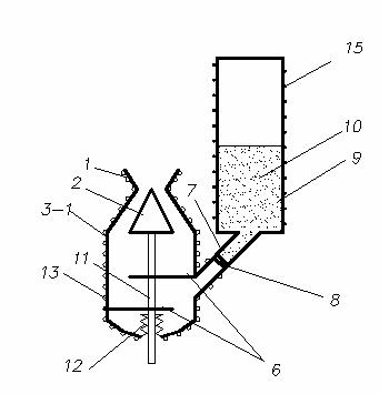
[0028] Example 2: see figure 2 , the vacuum evaporation system that can control the distribution and composition of the evaporation airflow is a simplified structure of embodiment 1. In this embodiment, the whole system is simplified as consisting of a high-temperature vacuum evaporation gun (3), a feeding valve (8) and a storage tank (9 )composition. The high-temperature vacuum evaporation gun (3) here combines the functions of the high-temperature vacuum evaporation gun (3), the high-temperature pipeline (4), and the high-temperature evaporation crucible (5) in Example 1. The vacuum evaporation gun here is used both as an evaporation gun and as an evaporation crucible. The high temperature vacuum evaporation gun is made of high temperature resistant materials such as molybdenum, tantalum, stainless steel and other materials. The up and down of the spout is all tapered such a spout itself has the function of divergence, and there is also a gas guide plug (12) below the spo...

Embodiment 3

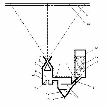
[0029] Embodiment 3: see image 3 , the vacuum evaporation system that can control the distribution and composition of the evaporating air flow is basically the same as that of Embodiment 1. The difference between this embodiment and Embodiment 1 is that there is a through-hole on the top of the high-temperature vacuum evaporation gun (3) in the entire system. A mask plate (17) and a substrate (16). It shows that due to the use of the high-temperature vacuum evaporation gun (3) of Example 1, a uniform vacuum evaporation gas flow can be obtained for the substrate directed upward by the high-temperature vacuum evaporation gun. Molecules of the evaporated gas basically move in a straight line, so even if the mask plate is not in close contact with the substrate, a better upward mask projection effect can still be obtained.


PUM


Abstract

The invention relates to a vacuum evaporation system capable of controlling evaporating airflow distribution and components. The system comprises an evaporation gun, a high-temperature evaporation crucible and a storage tank filled with an evaporating material, wherein a nozzle with an upper conical surface and a lower conical surface is formed on the evaporation gun, and a movable airflow guidance plug is arranged inside the nozzle; a substrate to be evaporated is opposite to the front of the nozzle; the evaporation gun is connected with the high-temperature evaporation crucible which is provided with a cross baffle through a heat pipeline or a surge flask, and the other side of the crucible is connected with the storage tank through a pipeline which is provided with a feed valve; heating coils are arranged on the evaporation gun, the heat pipeline, the high-temperature evaporation crucible and the outer wall of the pipeline, and a heat coil is arranged on the outer wall of the storage tank as well; the evaporating material in the storage tank is delivered into the high-temperature evaporation crucible through the feed valve and the pipeline, so that the evaporating material to be evaporated is immediately turned to be vapor delivered to the evaporating gun; and the volume and the direction of the vapor can be controlled by changing the relative position of the airflow guidance plug and the nozzle, and the vapor is evaporated to the substrate to form an evaporating film, which is uniform and has set area and multiple components. The vacuum evaporation system has simple structure, can improve the utilization rate of the organic evaporating material, and can improve the production efficiency.

Description

technical field [0001] The invention relates to evaporation of organic and inorganic evaporating materials onto substrates for the production of organic light-emitting diodes (OLEDs), organic thin-film transistors (TFTs), organic solar cells, semiconductor devices, flat panel display devices, and other organic and inorganic devices. The vacuum evaporation system that can control the evaporation air flow distribution and composition. Background technique [0002] The vacuum evaporation process has been widely used in the manufacture of semiconductor components and flat panel display devices. Especially organic light-emitting diodes (OLEDs) have formed a large industry. The main process in the preparation of OLEDs is vacuum evaporation, which is to put the organic evaporation material in a heated crucible and turn the evaporation material into steam. deposited on the substrate. As the area of ​​the flat panel display continues to expand, the requirements for the uniformity...

Claims


Application Information

Patent Timeline
Patent Type & Authority Applications(China)
IPC IPC(8): C23C14/24C23C14/12
Inventor 张志林蒋雪茵张建华
Owner SHANGHAI UNIV
Why Eureka
Try Eureka