Timing drive mechanism for motorcycle engine

A transmission mechanism and engine technology, which is applied to engine components, machines/engines, transmissions, etc., can solve the problems of timing chains, increased wear of tension plates, inconvenient maintenance of engine gas turbine parts, and shortened life of parts, etc., to achieve Reduce the swing space, convenient and fast maintenance and inspection, and prolong the service life

Inactive Publication Date: 2011-04-13
CHONGQING CONSTR ELECTROMECHANICAL CO LTD
View PDF5 Cites 9 Cited by
  • Summary
  • Abstract
  • Description
  • Claims
  • Application Information

AI Technical Summary

Problems solved by technology

Eventually, the wear of the timing chain and the tension plate will increase, the abnormal noise of the engine will increase, and the life of the parts will be shortened.
[0008] The second defect is that when checking and maintaining the engine, it is often necessary to check and repair the gas turbine part. When checking and repairing the gas turbine part, it is not necessary to open the crankcase, just remove the cylinder head.
When the maintenance is completed and reinstalled, the timing chain needs to be put on the crankshaft sprocket again. However, since the crankshaft sprocket is located in the crankcase and cannot be seen, it is difficult to put it on. At this time, the crankcase also needs to be disassembled (originally No need), all the parts around the crankshaft sprocket can be removed, and then the timing chain can be put on, and then reinstalled, which is time-consuming and laborious, so this kind of tensioning device is extremely inconvenient for the maintenance of the gas turbine part

Method used


Image

  • Timing drive mechanism for motorcycle engine
  • Timing drive mechanism for motorcycle engine
  • Timing drive mechanism for motorcycle engine

Examples


Embodiment Construction

[0022] The structure of the present invention will be further described in detail below in conjunction with the accompanying drawings and specific embodiments.

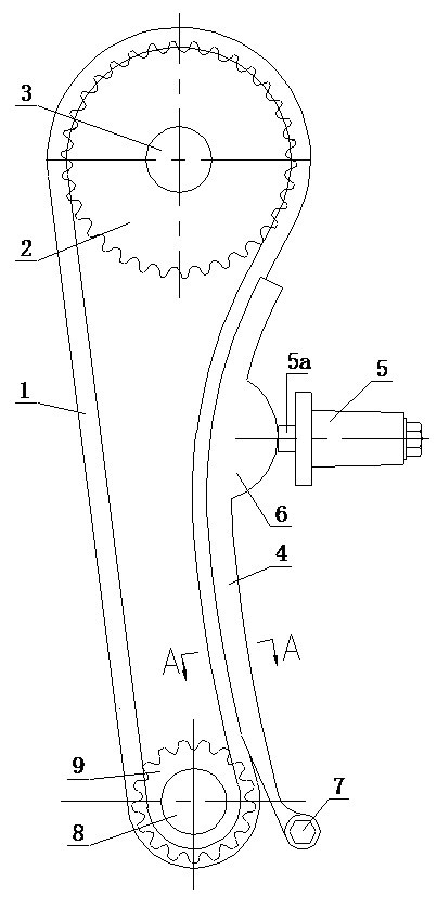
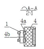
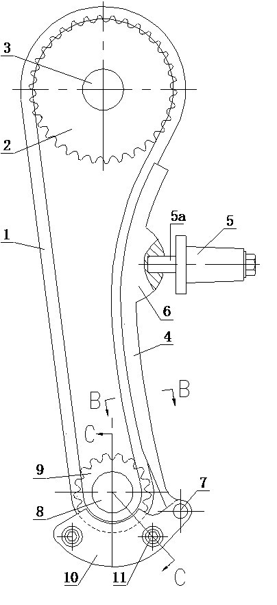
[0023] When the present invention is implemented, as Figure 3 to Figure 5 As shown, a timing transmission mechanism of a motorcycle engine includes a timing chain 1 and a tensioning device; one end of the timing chain 1 is sleeved on the crank sprocket 9 fixed to the crankshaft 8, and the other end of the timing chain 1 It is sleeved on the timing sprocket 2 fixed on the gas distribution camshaft 3; the tensioning device includes a tensioning plate 4 and a tensioning device 5, the tensioning plate 4 is in the shape of a strip with elasticity as a whole, and the tensioning plate 4. The lower end is fixed on the crankcase. One side of the tensioning plate 4 is in a convex arc shape and attached to the timing chain 1. The other side of the tensioning plate 4 has a convex hull 6; the tensioner 5 is fixed on There is a t...


PUM


Abstract

The invention discloses a timing drive mechanism for a motorcycle engine, which comprises a timing chain and a tensioning device. The tensioning device comprises a tensioning plate and a tensioner; one side of the tensioning plate is in a convex arc shape and is attached to the timing chain, and the other side of the tensioning plate is provided with a convex bag; the tensioner is fixed on a cylinder body and is provided with a tensioning rod; and one end of the tensioning rod is arranged in the tensioner, and the other end of the tensioning rod stretches out under the action of a spring and is opposite to the convex bag. The improvement is that: the bottom of a groove is provided with a smooth plane; the coordination distance between the timing chain and the side wall of the groove is less than 0.1mm; the convex bag is provided with a limiting hole; one end of the tensioning rod opposite to the convex bag is positioned in the limiting hole and is in interference fit with the limiting hole; and a limiting plate is arranged below a crankshaft sprocket. The timing drive mechanism has the advantages of small vibration, low noise, long service life, convenience of maintenance and the like.

Description

[0001] technical field [0002] The invention relates to the field of motorcycle engines, in particular to a timing transmission mechanism of a motorcycle engine. [0003] Background technique [0004] The timing transmission mechanism of motorcycle engine is a transmission mechanism used between the crankshaft of motorcycle engine and the valve camshaft, including timing chain and tensioning device. The timing chain generally adopts roller chain, and its main function is It transmits the power of the engine crankshaft to the valve camshaft, and then drives the opening and closing of the intake and exhaust valves to realize the intake, exhaust, compression and work of the engine; since the length of the timing chain is an integer multiple of the fixed pitch, Generally, they are longer than the actual needs, so the chain drive needs to be designed with a tensioning device, which is used to tension the timing chain. [0005] The most common existing motorcycle engine timing ...

Claims


Application Information

Patent Timeline
Patent Type & Authority Applications(China)
IPC IPC(8): F01L1/348F16H7/08
Inventor 兰华徐凤雏
Owner CHONGQING CONSTR ELECTROMECHANICAL CO LTD
Why Eureka
Try Eureka