Water cooling structure for multi-cylinder engine

A multi-cylinder engine, water cooling technology, applied in the direction of engine cooling, engine components, machine/engine, etc., can solve the problem of independent cooling, cooling uniformity and cooling performance consistency cannot be well guaranteed, and can not achieve uniform cooling of the combustion chamber And other issues

Active Publication Date: 2011-04-13
DONGFENG MOTOR CORP HUBEI
View PDF4 Cites 2 Cited by
  • Summary
  • Abstract
  • Description
  • Claims
  • Application Information

AI Technical Summary

Problems solved by technology

Its disadvantages are: it is difficult to control the flow of coolant in the cylinder body and cylinder head, and the uniformity of cooling and the consistency of cooling performance of each cylinder should not be well guaranteed.
[0003] The Chinese Patent Office discloses a cooling system for engines, the publication number is CN1786433A, the feature of this patent is that the cooling system is designed as a structure independent of the water flow channel of the cylinder block and the water flow channel of the cylinder head, and the two cooling streams supplied by the water pump The water is used to cool the cylinder block and the cylinder head separately, but ther...

Method used


Image

  • Water cooling structure for multi-cylinder engine
  • Water cooling structure for multi-cylinder engine
  • Water cooling structure for multi-cylinder engine

Examples


Embodiment Construction

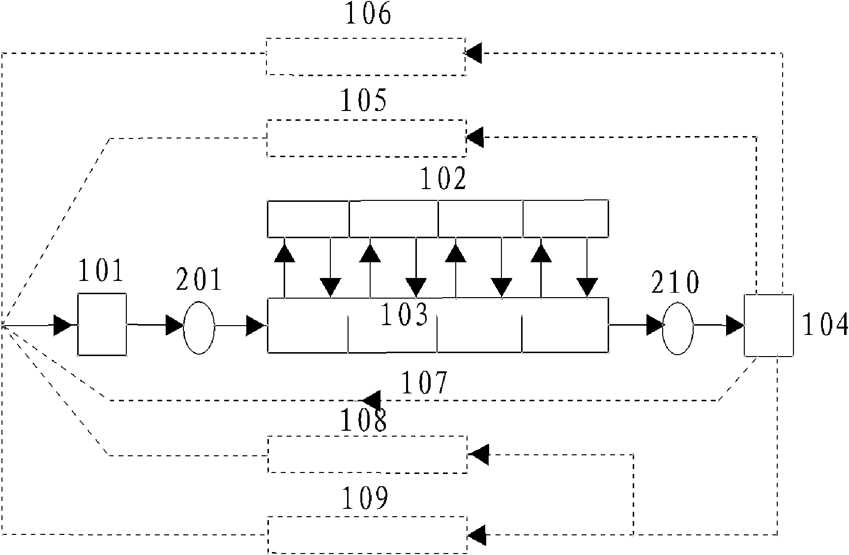
[0021] Such as figure 1 As shown, the cooling system for the multi-cylinder engine includes a water pump 101, a cylinder block cooling water flow channel 103, a cylinder head cooling water flow channel 102, a thermostat 104, a radiator 109, an oil cooler 106, a liquid storage bottle 108, and a heating ventilator 105 and small circulation pipe 107. Wherein thermostat 104, radiator 109, engine oil cooler 106, liquid storage bottle 108, heating ventilator 105 and small circulation pipe 107 adopt existing common arrangement form to communicate with each other.

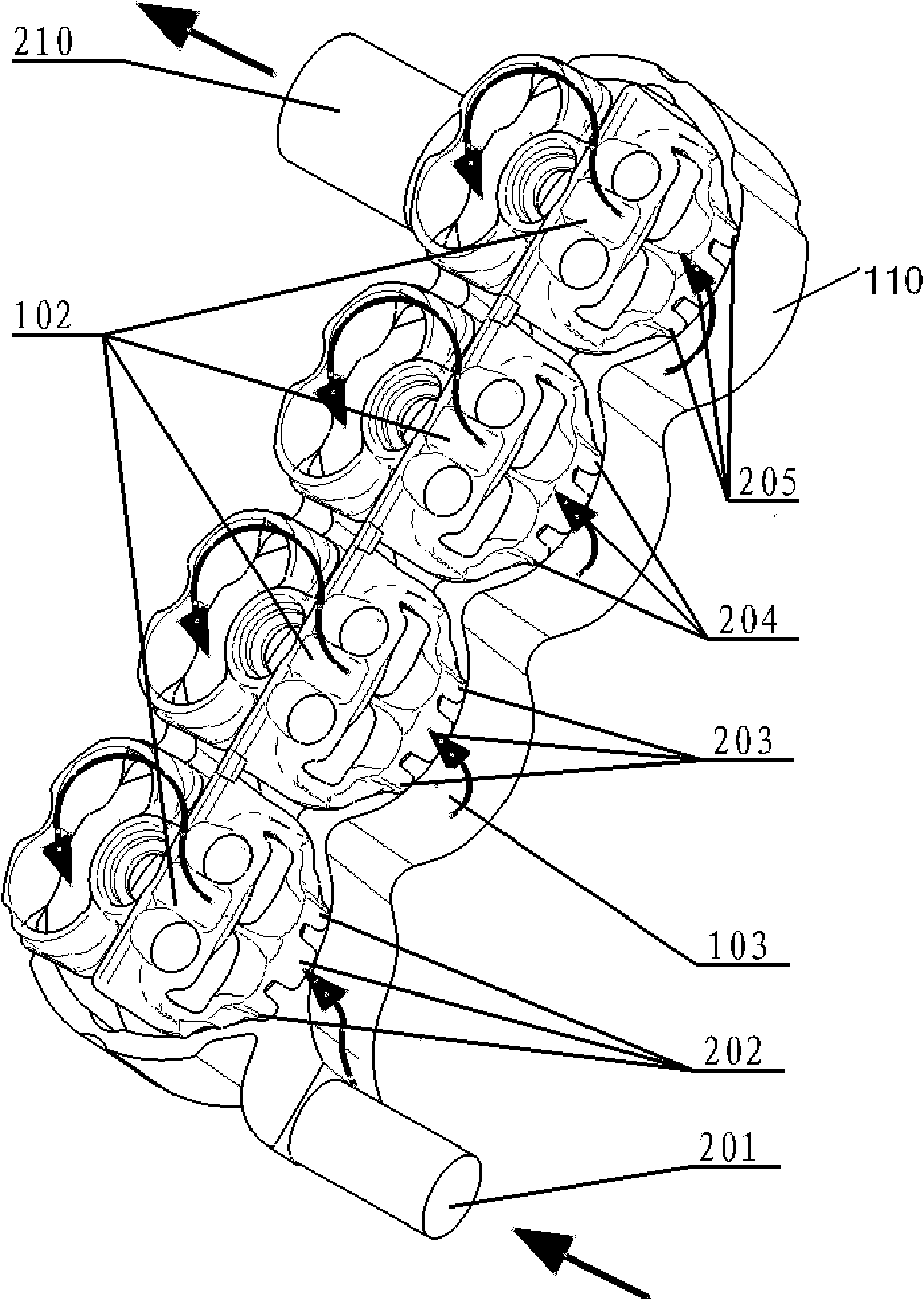
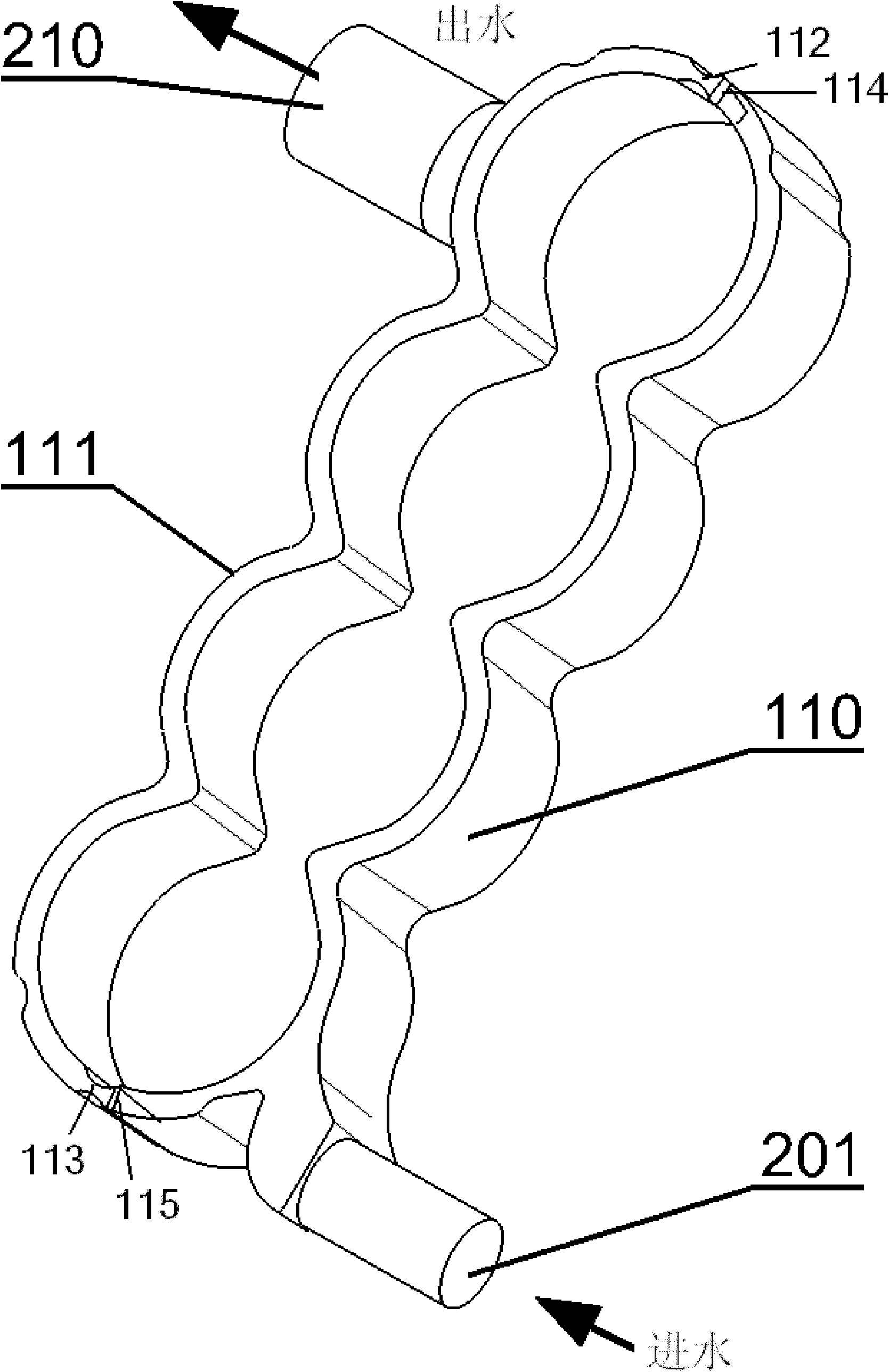
[0022] Such as image 3 As shown, the cylinder block cooling water channel 103 is cast in the area surrounding the piston cylinder in the multi-cylinder engine block, and the cylinder block cooling water channel 103 is divided into the front exhaust side cylinder cooling water channel section 110 and the rear intake side cylinder block Two damping holes 112, 113 are provided between the cooling water flow passage section...


PUM


Abstract

The invention discloses a water cooling structure for a multi-cylinder engine. The structure comprises a cylinder body cooling water flow channel and a cylinder cover cooling water flow channel, wherein the cylinder body cooling water flow channel is provided with an water inlet of the cylinder body cooling water flow channel and a water outlet of the cylinder body cooling water flow channel; a water flow damping device is arranged in the cylinder body cooling water flow channel; the cylinder body cooling water flow channel is divided into a front section and a rear second by the water flow damping device; the cylinder cover cooling water flow channel surrounds all the cylinder combustion chamber regions; the cylinder cover cooling water flow channel of each cylinder combustion chamber region is provided with a cylinder cover water inlet and a cylinder cover water outlet; the top of the cylinder cover cooling water flow channel is communicated with an exhaust pipe; the cylinder cover water inlet of the cylinder cover cooling water flow channel of each cylinder combustion chamber region is communicated with the cylinder body cooling water flow channel at the front section of the water flow damping device; and the cylinder cover water outlet of the cylinder cover cooling water flow channel of each cylinder combustion chamber region is communicated with the cylinder body cooling water flow channel at the rear section of the water flow damping device. The structure ensures that each combustion chamber of a cylinder cover can be uniformly cooled by cooling water and avoids influence of local overheating of the cylinder cover on the engine performance.

Description

technical field [0001] The invention belongs to automobile engine cooling technology, in particular to a multi-cylinder engine water cooling structure. Background technique [0002] At present, the cooling water flow scheme generally adopted in the existing engine cooling system is as follows: firstly, the water with a lower temperature after being cooled by the radiator is pumped into the front end of the cylinder through the water pump and sent to the water diversion channel on the side of the cylinder, and then the main water flow It flows through the gap between the cylinder barrels to the other side of the cylinder barrel, flows upwards into the cylinder head through the water hole between the cylinder block and the cylinder head, and then flows through the high temperature area of ​​the combustion chamber near the center of each cylinder of the cylinder head, and finally by Concentrated outflow from the outlet pipe of the cylinder head. Its disadvantages are: it is di...

Claims


Application Information

Patent Timeline
IPC IPC(8): F01P3/02
Inventor 许立兵田宁周洪光章帅韬
Owner DONGFENG MOTOR CORP HUBEI
Why Eureka
Try Eureka