
Locking device in solar module framing and cornering device

A technology of solar cells and locking devices, applied in electrical components, circuits, semiconductor devices, etc., can solve the problems of limited use of promotion, high labor intensity, high energy consumption, etc., achieve huge economic and social benefits, and improve work efficiency. and production efficiency, the effect of reducing labor intensity

Inactive Publication Date: 2012-09-19
YINGKOU JINCHEN MACHINERY
View PDF3 Cites 0 Cited by
  • Summary
  • Abstract
  • Description
  • Claims
  • Application Information

AI Technical Summary

Problems solved by technology

With the rapid development of energy-saving manufacturing industry and the increase of its market demand, the existing production technology of solar cells is no longer suitable for the development needs of large-scale, standardized, automated and functional; its production is greatly restricted, no matter from the production The process, production efficiency, product quality, process consistency and product appearance cannot meet the production requirements. The main problems are: 1. The production efficiency of the frame is low; 2. The quality of the riveting angle is unstable and the equipment structure is unreasonable; 3. 1. Poor rigidity, does not meet the technical requirements of components; 4. High scrap rate; 5. High labor intensity; 6. Poor aesthetics
[0003] In addition, some foreign manufacturers of solar cell module equipment adopt a process of placing the manipulator into the profile frame through repeated reciprocating movements. frame, but the time it takes to take out the frame and install the frame is about the same as the labor, and the manipulator equipment is expensive, the maintenance cost is high, the floor area is large, and the energy consumption is large
At present, domestic promotion and use have been greatly restricted and are not suitable for my country's national conditions.

Method used


Image

  • Locking device in solar module framing and cornering device
  • Locking device in solar module framing and cornering device
  • Locking device in solar module framing and cornering device

Examples


Embodiment Construction

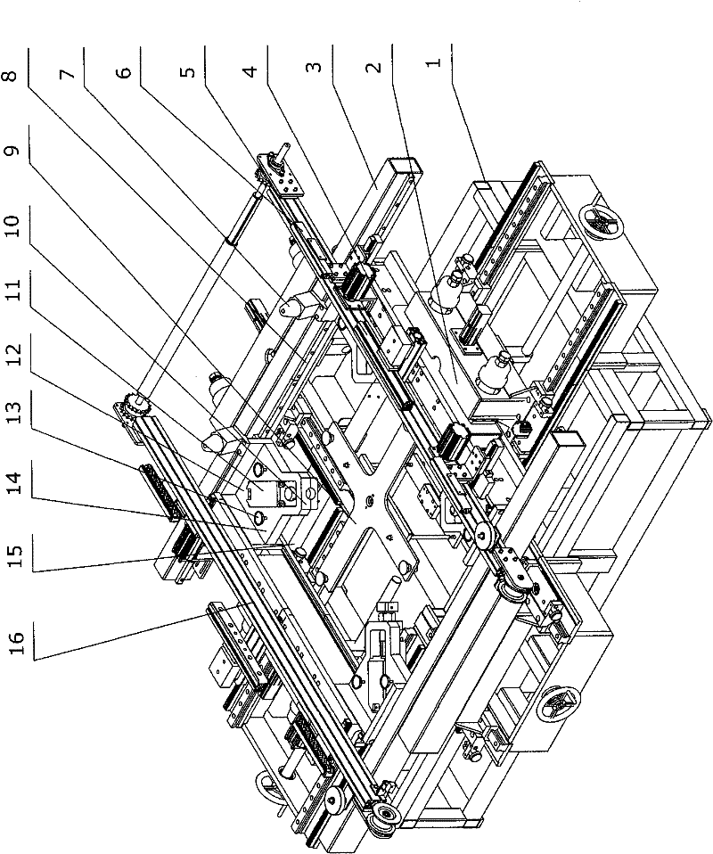
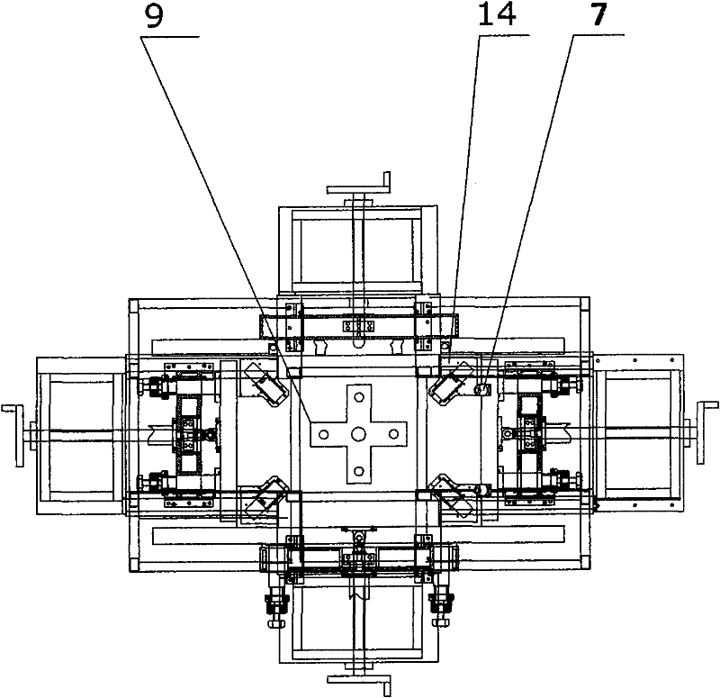
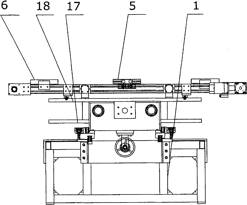
[0016] The present invention comprises frame 1, and one side of frame 1 is provided with movable support 2, and the top of frame 1 is provided with group frame crossbeam 3, and movable support 2 is fixedly connected with group frame crossbeam 3; The upper guide plate 18 and the lower guide plate 17 link to each other, and the lower guide plate 17 fixes the group angle bottom plate 15 of the group angle oil cylinder 10 to link to each other with the group frame beam 3, and is fixed on the group angle bottom plate 15 on the inner peripheral angle of the frame 1 to be provided with a group Angle mechanism14.

[0017] The group angle mechanism 14 is connected by the group angle knife 11 on the group angle plate 12 and the group angle oil cylinder 10 fixed on the group angle base plate 15, and the group angle plate 12 is provided with a support suction cup 13; the group angle plate 12 The number is four.

[0018] The front end of the group angle body in the group angle knife 11 ca...


PUM


Abstract

The invention provides a locking device in a solar module framing and cornering device, and relates to production equipment of solar modules, in particular to the locking device in the solar module framing and cornering device, which has a simple structure and high automation degree. The locking device comprises a frame, and is characterized in that: movable supports and a framing cross beam are arranged on the one side of the frame, a framing cross beam is arranged above the frame, and a movable support is fixedly connected with the framing cross beam; the framing cross beam is connected with an upper guide plate and a lower guide plate respectively; a cornering bottom plate of the lower guide plate for fixing a cornering hydro-cylinder is connected with the framing cross beam; and a cornering mechanism is arranged on the cornering bottom plate which is fixed on the inner round angle of the frame.

Description

Technical field: [0001] The invention relates to a production equipment of a solar battery module, in particular to a locking device in a solar battery module frame and corner device. Background technique: [0002] At present, most of the enterprises in the packaging and production of solar cell modules adopt the form of single unit frame, single unit corner, semi-manual and non-continuous operation. That is: first manually knock the "corner code" of the aluminum profile connector into the profile connection cavity with a rubber hammer; then put the solar cell (laminated glass) into the profile slot, and then manually carry the assembly and put it into the group frame After the framing process is completed, the components are manually lifted out and transferred to the corner forming machine for single-corner riveting process; in addition, a framing machine that has appeared in recent years uses pneumatic framing , Combined process of hydraulic group corners, this process me...

Claims


Application Information

Patent Timeline
Patent Type & Authority Patents(China)
IPC IPC(8): H01L31/18
CPCY02P70/50
Inventor 李敦信
Owner YINGKOU JINCHEN MACHINERY
Learn More