Rotor position detection device

A rotor position detection and rotor technology, applied in the field of rotor position devices, can solve problems such as motor stop, rotation speed error, noise, etc.

Active Publication Date: 2011-04-20
TOSHIBA LIFESTYLE PROD & SERVICES CORP +1
View PDF6 Cites 15 Cited by
  • Summary
  • Abstract
  • Description
  • Claims
  • Application Information

AI Technical Summary

Problems solved by technology

As a result, a large error occurs in the detected rotor position and rotation speed, and if the motor is controlled based o

Method used


Image

  • Rotor position detection device
  • Rotor position detection device
  • Rotor position detection device

Examples


Embodiment Construction

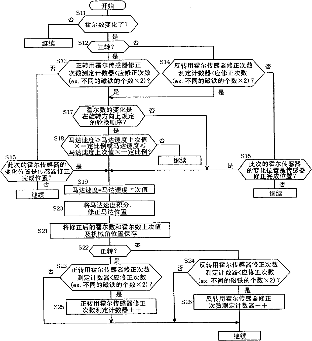
[0029] Below, refer to Figure 1 to Figure 12 An example will be described. Figure 8 It is a plan view showing the structure of the rotor of the permanent magnet motor 1 (outer rotor type brushless motor). A permanent magnet motor 1 is composed of a stator 2 and a rotor 3 provided on its outer periphery. The stator 2 is composed of a stator core 4 and a stator winding 5 . The stator core 4 is formed by laminating a plurality of die-cut soft magnetic silicon steel sheets, and has an annular yoke portion 4a and a plurality of teeth portions 4b protruding radially from the outer peripheral portion of the yoke portion 4a. . The surface of the stator core 4 is covered with PET resin (casting resin) except for the front end surface of each tooth portion (tees portion) 4 b.

[0030] In addition, a plurality of mounting portions 6 made of the PET resin are integrally formed on the inner peripheral portion of the stator 2 . These mounting parts 6 are provided with a plurality of ...


PUM


Abstract

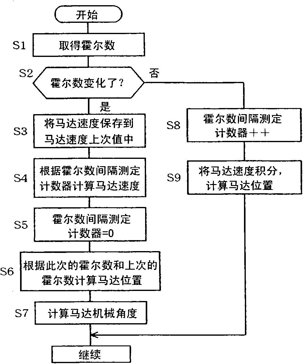
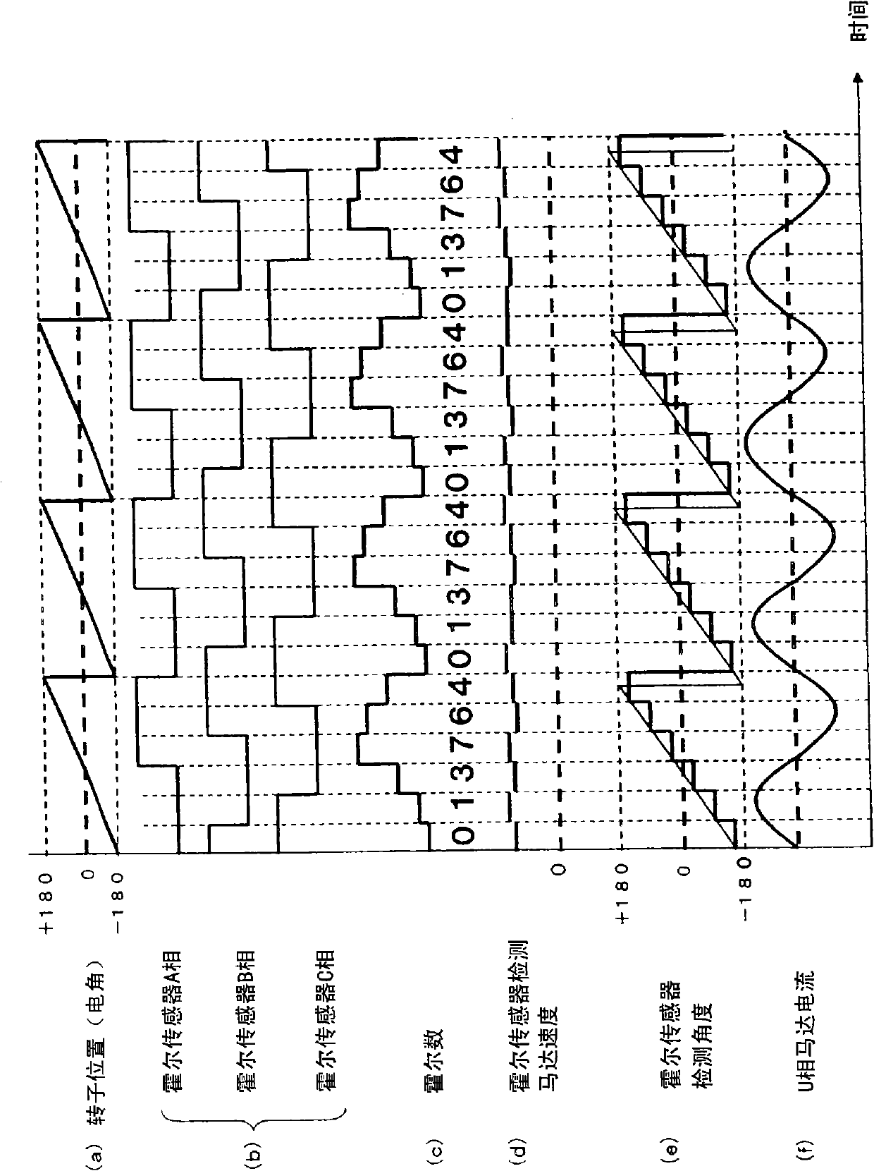
The invention relates to a rotor position detection device. A magnetic detection sensor with low costs can be used to detect the position of a rotor correctly, when a permanent magnet motor disposed in the rotor is provided with a plurality of permanent magnets, parts of which have different magnetic forces. The permanent magnet motor (1) disposed in the rotor (3) is provided with two magnets, one is a neodymium magnet (9a) and the other is an alnico magnet (9b). 3 Hall sensors (68) (A,B,C) can be used by a speed. position detection part (55) to detect the rotation speed of the permanent magnet motor (1), and the position of the rotor (3) can be detected based on the rotation speed. The rotation speed or the position of the rotor, which are detected by the speed. position detection part (55), can be corrected, when the speed. position detection part (55) detects the boundary between the neodymium magnet (9a) and the alnico magnet (9b) according to the changing state of the sensor signal output by the Hall sensors (68).

Description

technical field [0001] The present invention relates to a device for detecting the rotor position of a permanent magnet motor in which a plurality of permanent magnets having different magnetic forces are arranged in the rotor. Background technique [0002] In recent years, in washing machines, the combination of a direct-drive permanent magnet motor and a motor control device using vector control has improved the control accuracy of the motor and improved washing performance, and achieved reduced power consumption and improved efficiency during washing operation. Effects such as vibration reduction. In a conventional general control method, when the motor is rotated at high speed by dehydration operation or the like, field weakening control is performed to reduce the induced voltage of the motor by passing a d-axis current Id that does not act on torque. In this case, during the spin-drying operation, a current that does not contribute to the torque always flows, which inc...

Claims


Application Information

Patent Timeline
IPC IPC(8): H02K29/08H02P27/04H02P6/06H02P6/08H02P6/16H02P6/17H02P6/182H02P21/00H02P21/04H02P21/05H02P23/03H02P23/04H02P27/08
CPCD06F33/00G01D5/244H02P6/06H02P6/16H02P21/06H02P2203/03
Inventor 前川佐理细丝强志
Owner TOSHIBA LIFESTYLE PROD & SERVICES CORP
Why Eureka
Try Eureka