Method, repeater and communication system for positioning submarine cable failure,

A repeater and fault technology, applied in the field of communication, can solve the problems of accumulating ASE noise, long time for locating submarine cable faults, failure to find fault points in time, etc.

Active Publication Date: 2011-04-20
HUAWEI TECH CO LTD
View PDF3 Cites 21 Cited by
  • Summary
  • Abstract
  • Description
  • Claims
  • Application Information

AI Technical Summary

Problems solved by technology

[0009] During the research and practice of the prior art, the inventors of the present invention found that in the existing method for locating the fault of the submarine cable system, when the detection light returns to the COTDR, it needs to pass through multiple EDFAs, which will accumulate ASE noise, resulting in the need

Method used


Image

  • Method, repeater and communication system for positioning submarine cable failure,
  • Method, repeater and communication system for positioning submarine cable failure,
  • Method, repeater and communication system for positioning submarine cable failure,

Examples


Embodiment 1

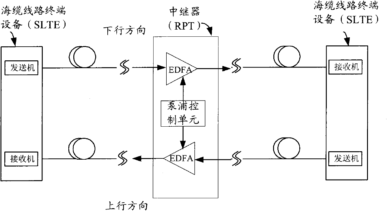
[0039] An embodiment of the present invention provides a communication system, still refer to Figure 4 As shown, including: submarine cable line terminal equipment 401 and repeater (RPT, Repeater) 402;

[0040] Among them, the above-mentioned submarine cable line terminal equipment 401 is used to obtain the span to which the fault is located, and send an execution positioning detection command to the repeater 402 on the span; receive the time T1 and time T3 sent by the repeater 402 , or receive the time difference between the time T3 and the time T1 sent by the repeater 402; according to the time T1 and the time T3, or any one of the time difference between the time T3 and the time T1, and according to the OTDR principle, the formula: d= (c*t) / (2IOR), to obtain the location of the fault, where d is the distance from the location where the detection light pulse is generated to the location of the fault, c is the propagation speed of light in a vacuum, t=T3- T1, IOR is the ref...

Embodiment 2

[0047] An embodiment of the present invention provides a repeater, such as Figure 5 As shown, the repeater includes: a detection unit 501 and a sending unit 502 .

[0048] The above-mentioned detection unit 501 is used to receive the execution positioning detection command sent by the submarine cable line terminal equipment (SLTE); according to the received execution positioning detection command, trigger the generation of detection light pulses; transmit the detection light pulses along the SLTE sending direction to Where the fault is located; record the start time T1 and the end time T2 of the output detection light pulse; detect the detection light pulse reflected from the fault position; obtain the time T3 when the detection light pulse is detected.

[0049] Wherein, the detection unit 501 in the repeater is used to receive the execution positioning detection command sent by the submarine cable line terminal equipment (SLTE). The laser is connected to the erbium-doped fi...

Embodiment 3

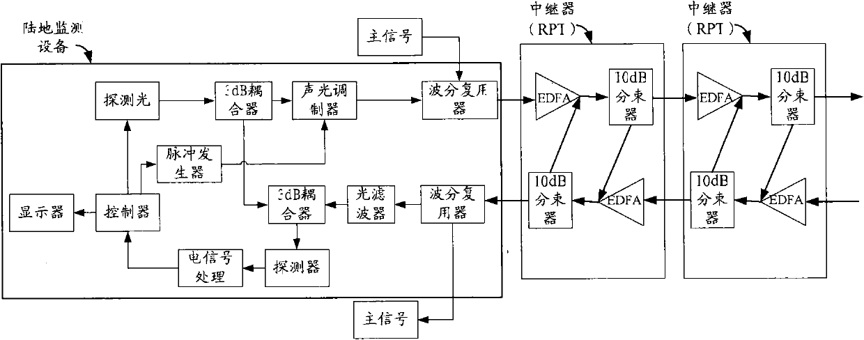
[0061] An embodiment of the present invention provides a repeater, such as Figure 6 As shown, the detection unit 501 of the repeater specifically includes: a first pump laser 601, a first erbium-doped fiber amplifier 602, an optical switch 603, a first detector 604, and a first controller 605; the sending unit 502 specifically includes : the fourth erbium-doped fiber amplifier 606.

[0062] Wherein, the first pumping laser 601 is used to generate pumping light according to the control of the first controller 605, and inject the generated pumping light into the first erbium-doped fiber amplifier 602 and the fourth erbium-doped fiber amplifier;

[0063] The first erbium-doped fiber amplifier 602 is configured to use the pump light generated by the first pump laser 601 to amplify the optical signal sent from the SLTE that contains the command to execute the positioning detection, and input the amplified optical signal to the first The controller 605; using the pump light generate...


PUM


Abstract

A method, a device and a communication system for locating submarine cable fault are disclosed by the embodiments of the present invention. The optical pulse output by the repeater(RPT) is transmitted to the fault point as the probe optical pulse; the RPT obtains the time difference between the probe optical pulse and the reflected optical pulse, and transmits the time difference to the terrestrial Submarine Line Terminal Equipment(SLTE), therefore the SLTE can easily locate the fault point according to the Optical Time Domain Reflector(OTDR) theory. Compared with the prior art, the method can locate the submarine fault point faster and more accurately, therefore the maintainer can maintain the fault in time.

Description

technical field [0001] The invention relates to the field of communication technology, in particular to a method for locating submarine cable faults, a repeater and a communication system. Background technique [0002] In recent years, with the maturity of dense wavelength division multiplexing (DWDM, Dense Wavelength-Division Multiplexing) technology and Erbium-doped Optical Fiber Amplifier (EDFA, Erbium-doped Optical Fiber Amplifer) technology, the large-capacity long-distance The number of communication systems continues to increase, and there are more and more international submarine cable communication systems. Therefore, the rapid and accurate location of the fault of the submarine cable line enables the maintenance personnel to quickly repair the fault, and can reduce the cost of operating the submarine cable communication system. [0003] Generally, a submarine cable system includes: two submarine cable line terminal equipment (SLTE, Submarine Line Terminal Equipmen...

Claims


Application Information

Patent Timeline
IPC IPC(8): H04B10/08H04B10/16H04B10/17H04J14/02H04B10/071H04L69/40
CPCG01M11/3145H04B10/071G01M11/3109
Inventor 张森冯志勇
Owner HUAWEI TECH CO LTD
Why Eureka
Try Eureka