Arrangement structure of evaporated fuel treatment device of saddle-ride-type vehicle

A technology for evaporating fuel and processing device, which is applied in the field of configuration structure of evaporative fuel processing device, can solve the problems of affecting carbon canister, affecting the effect of evaporative fuel emission, and raising carbon canister, etc., and achieves the promotion of absorption performance, easy cooling, and promotion of emission performance. Effect

Active Publication Date: 2011-04-27
HONDA MOTOR CO LTD
View PDF7 Cites 8 Cited by
  • Summary
  • Abstract
  • Description
  • Claims
  • Application Information

AI Technical Summary

Problems solved by technology

[0006] However, in the above-mentioned prior art, the carbon tank is arranged in front of the engine and outside the downtube of the vehicle frame, so that the carbon tank will be cooled by the running wind generated by driving when the vehicle is running, thereby affecting the air in the carbon tank. The emission effect of evaporated fuel, and the temperature of the carbon tank will increase due to direct sunlight and other reasons when the vehicle stops, which will affect the absorption of evaporated fuel by the carbon tank

Method used


Image

  • Arrangement structure of evaporated fuel treatment device of saddle-ride-type vehicle
  • Arrangement structure of evaporated fuel treatment device of saddle-ride-type vehicle
  • Arrangement structure of evaporated fuel treatment device of saddle-ride-type vehicle

Examples


Embodiment Construction

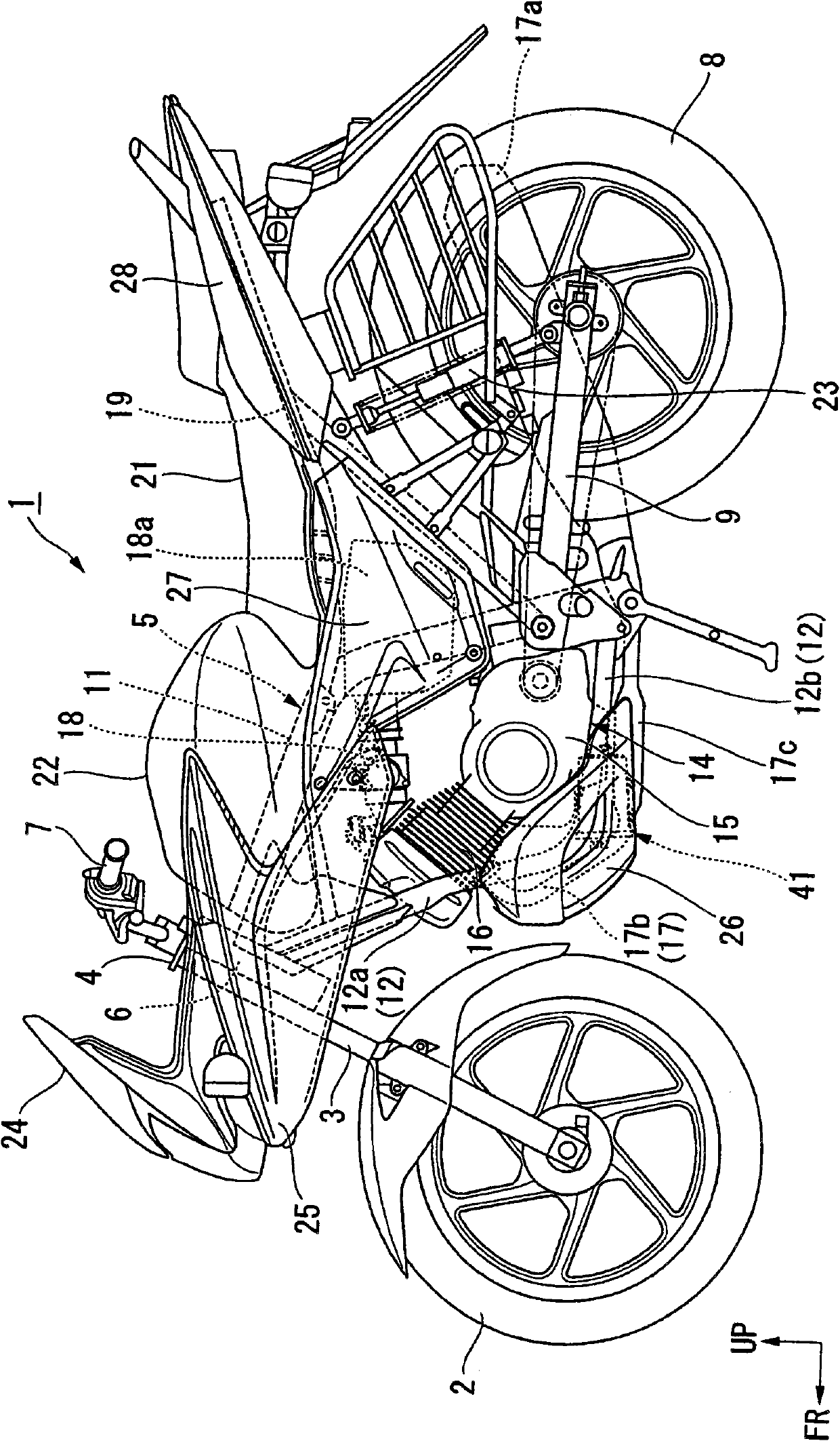
[0060] Next, specific embodiments of the present invention will be described with reference to the drawings. In the following description, unless otherwise specified, directions such as front, rear, left, and right refer to the vehicle. In addition, arrows FR, LH, and UP in the figure indicate the vehicle front, left direction, and right direction, respectively.

[0061] exist figure 1 In the motorcycle (saddle type vehicle) 1 shown, the front wheel 2 is rotatably supported by the lower end of the front fork 3 . The upper part of each front wheel fork 3 is pivotally supported on the front tube 6 at the front end of the vehicle frame 5 through the steering main rod 4, and can be operated. A handle 7 for steering the front wheels is attached to the top of the steering main rod 4 . The rear wheel 8 of the motorcycle 1 is rotatably supported by a rear end portion of a swing arm 9 .

[0062] The vehicle frame 5 mainly includes a main frame 11 and a pair of left and right down t...


PUM


Abstract

To enable mounting of a canister on a vehicle body in a compact manner while favorably ensuring the charge performance and the purge performance of the canister in the arrangement structure of an evaporated fuel treatment device of a saddle-ride-type vehicle. An under cowl (26) is provided at a front side of a lower portion of an engine (14), and a canister (41) is arranged below the engine (14) and inside the under cowl (26).

Description

technical field [0001] The present invention relates to an arrangement structure of an evaporated fuel processing device which is equipped on a straddle vehicle such as a motorcycle and collects fuel gas evaporated in a fuel tank. Background technique [0002] Conventionally, it is known to install an evaporated fuel processing device (for example, a carbon canister) on a motorcycle (for example, refer to Patent Document 1). [0003] [Prior Art Literature] [0004] 【Patent Literature】 [0005] Patent Document 1: Japanese Utility Model Publication Publication No. 3-29573 [0006] However, in the above-mentioned prior art, the carbon tank is arranged in front of the engine and outside the downtube of the vehicle frame, so that the carbon tank will be cooled by the running wind generated by driving when the vehicle is running, thereby affecting the air in the carbon tank. The emission effect of evaporated fuel, and the temperature of the carbon tank will increase due to dire...

Claims


Application Information

Patent Timeline
Patent Type & Authority Applications(China)
IPC IPC(8): B62J37/00F02M25/08
CPCB60Y2200/12B60K2015/03514B62J37/00B60K15/03504
Inventor 关弘幸
Owner HONDA MOTOR CO LTD
Why Eureka
Try Eureka