
Traveling wave fault location method for transmission line based on electronic transformer

An electronic transformer, traveling wave fault technology, applied in radio wave measurement systems, fault locations, emergency protection circuit devices, etc., can solve problems such as troublesome and inconvenient maintenance, and achieve the effect of improving reliability and improving distance measurement accuracy.

Inactive Publication Date: 2011-04-27
ELECTRIC POWER RES INST STATE GRID JIANGXI ELECTRIC POWER CO +1
View PDF3 Cites 19 Cited by
  • Summary
  • Abstract
  • Description
  • Claims
  • Application Information

AI Technical Summary

Problems solved by technology

However, this method needs to install two sets of traveling wave detection devices on the high-voltage transmission line between the two substations, which is very troublesome. Once the detection device fails, maintenance is very inconvenient

Method used


Image

  • Traveling wave fault location method for transmission line based on electronic transformer
  • Traveling wave fault location method for transmission line based on electronic transformer
  • Traveling wave fault location method for transmission line based on electronic transformer

Examples


Embodiment Construction

[0025] The specific embodiments of the present invention are as Figure 1 to Figure 4 Shown.

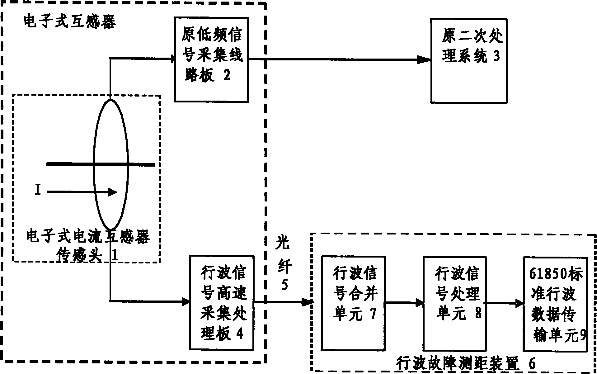
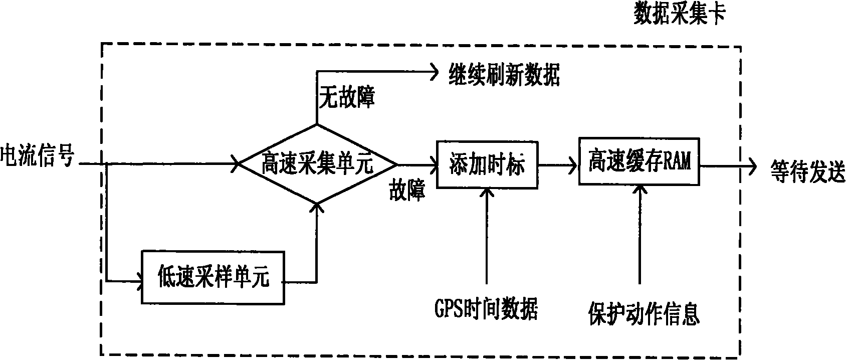
[0026] figure 1 It is a schematic diagram of the data processing flow of the present invention. Such as figure 1 As shown, the sampling frequency of the existing electronic transformer mainly meets the functional requirements such as protection and measurement. The sampling frequency is basically about 10kHz, which is difficult to meet the traveling wave ranging requirements. A separate high-speed data acquisition module must be added. Taking a current transformer as an example, the high-voltage sensor head 1 is composed of a Rogowisk coil and a collector circuit. The Rogowisk coil is used as a current sensor to output a small voltage signal proportional to the primary current. In order not to change the characteristics of the transformer and not affect the data collection of the original protection, measurement and other secondary processing system 3, on the basis of the original low-...


PUM


Abstract

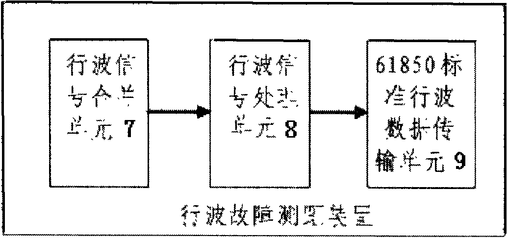
The invention relates to a traveling wave fault location method for a transmission line based on an electronic transformer, which is characterized by comprising the following steps: (a) adding a high-speed traveling wave signal data acquisition module 4 into the electronic transformer so as to meet the requirements for traveling wave fault location; (b) changing a signal input module of an original traveling wave fault location device into a digital signal input module which is applicable to the electronic transformer, wherein the digital signal input module mainly comprises a traveling wave signal merging unit 7, a traveling wave signal processing unit 8 and a traveling wave data transmission unit 9; and (c) carrying out communication between an optical digital signal of the electronic transformer and an optical fiber 5 of a traveling wave fault location device 6. The method provided by the invention has the advantages that by carrying out multi-item curve fitting on traveling wave fault signals, determining coefficients by using the least square method and reconstructing a dynamic process by using the obtained coefficients, the final data is the same as the traveling wave fault location data in conventional transformer substations, double-ended location and single-ended location analysis functions are implemented, and meanwhile, the location accuracy is ensured. The method provided by the invention is suitable for traveling wave fault location of intelligent transformer substations.

Description

Technical field [0001] The invention relates to a traveling wave fault location method of a transmission line based on an electronic transformer, which belongs to the technical field of power system relay protection. Background technique [0002] In order to be able to observe the transient traveling wave phenomenon on the transmission line on the secondary side, the voltage and current signal conversion circuit must have sufficient response speed. For example, assuming that the traveling wave propagation speed is equal to the speed of light, in order to control the ranging resolution within 500m, the rise time of the output signal of the voltage and current transient signal conversion circuit must be within 3.3us, and the cut-off frequency of the corresponding conversion circuit cannot be lower than 25kHz . [0003] With the development of smart grids, digital and intelligent substations have become a trend. In smart substations, because some primary and secondary equipment and ...

Claims


Application Information

Patent Timeline
IPC IPC(8): G01R31/08G01S11/02
CPCG01R31/085Y04S10/522H02H7/265
Inventor 辛建波黄瑶毛鹏
Owner ELECTRIC POWER RES INST STATE GRID JIANGXI ELECTRIC POWER CO
Learn More