Projection imaging method and system based on red, green and blue LED light sources

A technology of LED light source and imaging method, applied in the direction of light source, point light source, fixed light source, etc., can solve the problems of small light energy, affecting light transmission, fiber deformation, etc., and achieve the effect of improving brightness, high definition and pure spectrum

Inactive Publication Date: 2011-04-27
许崇良
View PDF13 Cites 7 Cited by
  • Summary
  • Abstract
  • Description
  • Claims
  • Application Information

AI Technical Summary

Problems solved by technology

At present, the optical fiber is mainly used to transmit optical signals, and the light energy is small. There is no report on the optical fiber used to transmit such as 20 lumens. , will deform the optical fiber of the polymer material and affect light transmission

Method used


Image

  • Projection imaging method and system based on red, green and blue LED light sources
  • Projection imaging method and system based on red, green and blue LED light sources
  • Projection imaging method and system based on red, green and blue LED light sources

Examples


Embodiment 1

[0041] A projection imaging method based on red, green and blue trichromatic LED light sources,

[0042] Red rectangular primary color light beams, green rectangular primary color light beams and blue rectangular primary color light beams formed by the red LED light source module 1, the green LED light source module 5 and the blue LED light source module;

[0043] Directly irradiate the red LCD liquid crystal imaging plate 2, the green LCD liquid crystal imaging plate 4 and the blue LCD liquid crystal imaging plate 6 respectively with the red rectangular primary color light beam, the green rectangular primary color light beam and the blue rectangular primary color light beam to form three primary color imaging light beams;

[0044] The three-primary-color imaging light beams are synthesized by the three-primary-color light synthesis module 3 into color imaging light beams, and projected by the imaging lens module 7 to form images.

[0045] as attached figure 1 As shown, the p...

Embodiment 2

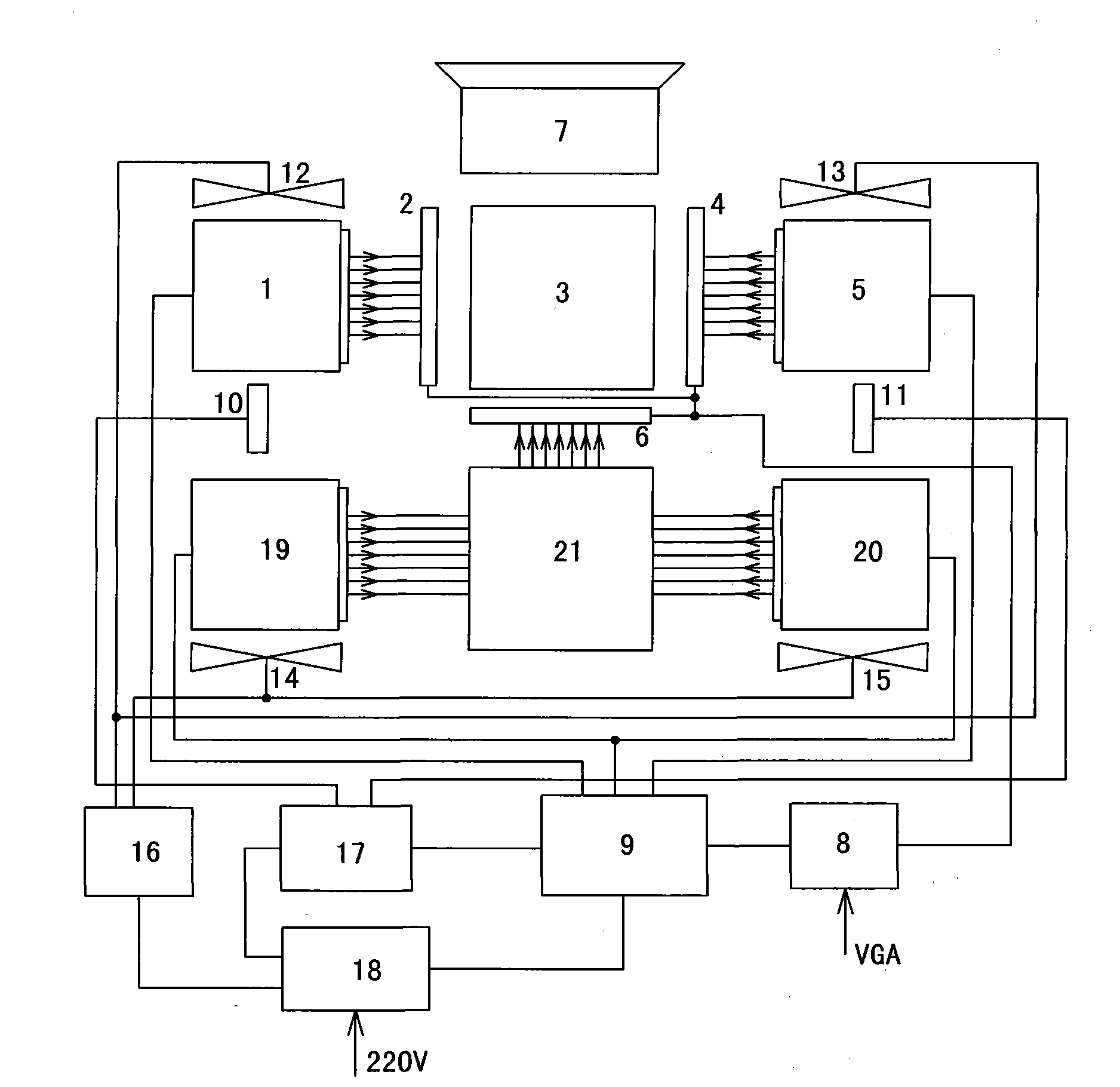
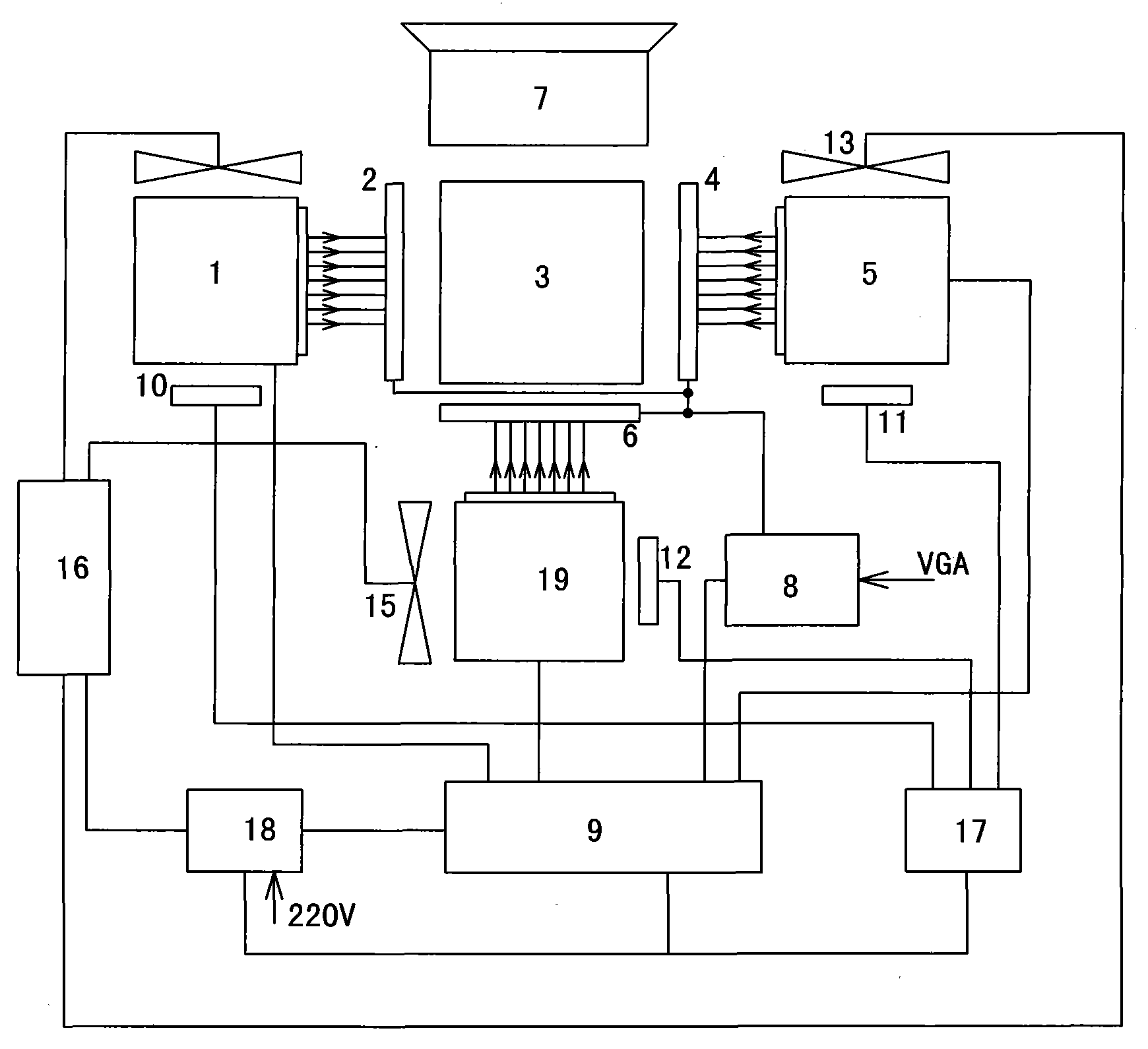
[0067] as attached figure 2 As shown, the projection imaging system for realizing the imaging method is mainly composed of a red LED light source module 1, a green LED light source module 5, a blue LED light source module 19, a red LCD liquid crystal imaging plate 2, a green LCD liquid crystal imaging plate 4, a blue LCD liquid crystal imaging board 6, trichromatic light synthesis module 3, imaging lens module 7, LCD liquid crystal imaging board driving module 8, LED light source driving power supply module 9, LED light source module temperature detection modules 10, 11, 12, LED light source module cooling fan 13 , 14, 15, cooling fan drive module 16, temperature control module 17 and power supply module 18 constitute.

[0068] Among them, the red LED light source module 1 , the green LED light source module 5 , and the blue LED light source module 19 are respectively used to generate a red rectangular primary color light beam, a green rectangular primary color light beam, an...


PUM


Abstract

The invention discloses a projection imaging method and system based on red, green and blue LED light sources, belonging to the field of optical projection imaging. The method comprises the following steps of: forming a three-color rectangular primary color light beam by using a red LED light source module, a green LED light source module and a blue LED light source module; respectively and directly radiating a three-color LCD liquid crystal imaging plate to form a three-primary-color imaging light beam by using the three-color rectangular primary color light beam; and synthesizing the three-primary-color imaging light beam into colored imaging light rays through a three-primary-color light synthesizing module, and projecting and imaging through an imaging lens module. All LED light rays are converged at a center of a sphere to form a high-brightness convergent point light source by using the geometrical theory that the diameter of the sphere passes through the center of the sphere and the crown concave surface of the sphere as a base plate of the LED light source modules, and the technical problem of short-distance convergence of an LED matrix light source is solved. Compared with the prior art, a projector manufactured with the method has the characteristics of low color temperature, small quantity of infrared rays and ultraviolet rays, no damageable parts such as electrodes, filaments and the like, no light loss caused by a spectroscope, high brightness, long service life and the like.

Description

technical field [0001] The invention relates to the field of optical projection imaging, in particular to a projection imaging method and system based on red, green and blue three primary color LED light sources. Background technique [0002] As a terminal display, the projector has small size, rich colors, large image size, high brightness, high contrast, light weight, and is easy to carry. It is widely used in classroom teaching, industry training, technical exchanges, entertainment and other fields. Existing projectors mainly use arc light source projection as the imaging principle: the conical light generated by the UHP arc lamp first passes through a filter to filter out infrared rays and ultraviolet rays. The light is uniformized through two multi-lens lenses and corrected into a rectangular light that approximates the projected image. Then the light is divided into the three primary colors of red, green and blue by the beam splitter and is respectively reflected to t...

Claims


Application Information

Patent Timeline
Patent Type & Authority Applications(China)
IPC IPC(8): G03B21/20G02B27/18G03B21/00G03B21/16F21V13/00F21V19/00F21Y101/02
Inventor 许崇良孙刚葛磊
Owner 许崇良
Why Eureka
Try Eureka