Filter, transmitter-receiver, and amplifying circuit
A technology for amplifying circuits and filters, applied in circuits, amplifiers, amplifiers with semiconductor devices/discharge tubes, etc., can solve problems such as fundamental wave signal attenuation
- Summary
- Abstract
- Description
- Claims
- Application Information
AI Technical Summary
Problems solved by technology
Method used
Image
Examples
no. 1 example
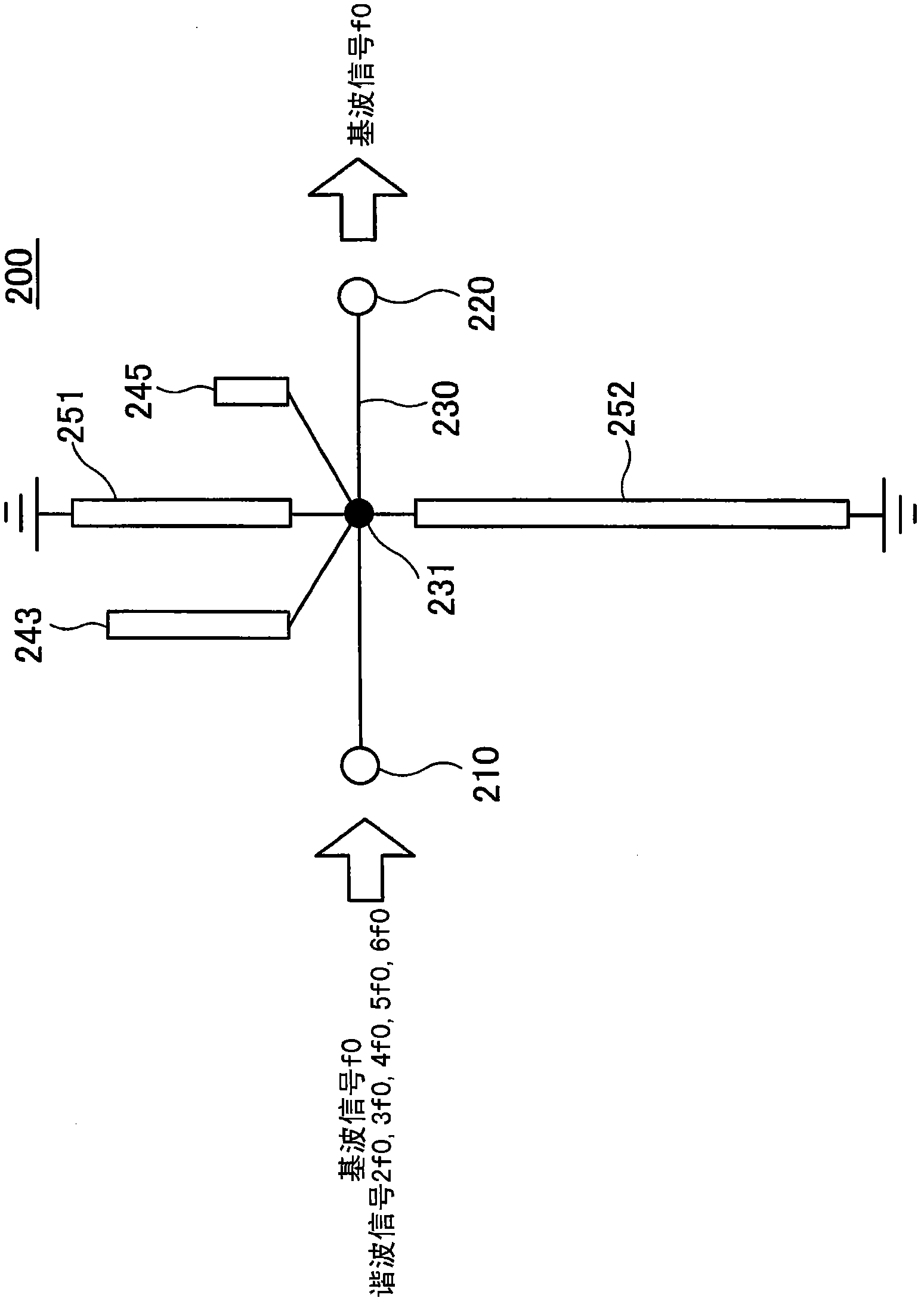
[0045] figure 2 An example of the filter according to the first embodiment is shown. The shown filter 200 according to the first embodiment includes an input terminal 210, an output terminal 220, a transmission line 230 connecting the input terminal 210 and the output terminal 220, open end stubs 243 and 245 coupled to the transmission line 230 through a connection node 231 and short-circuit stubs 251 and 252 . Here, the characteristic impedance Z0 of the transmission line 230 is 50Ω.
[0046] Such as figure 2 As shown, among the stubs connected to the transmission line 230 at one end, the stubs whose other ends are open are referred to as open end stubs 243 and 245, and the stubs whose other end is short-circuited are referred to as short end stubs. Lines (short-end stub) 251 and 252.
[0047] The fundamental wave signal f0 and harmonic signals having frequencies that are integer multiples of the fundamental wave signal f0 are provided to the input terminal 210 . Here,...
no. 2 example
[0067] The filter according to the second embodiment corresponds to a filter obtained by applying a microstrip line to the filter 200 according to the first embodiment.
[0068] Figure 7 is a perspective view showing an example of the filter according to the second embodiment. Figure 8 for Figure 7 top view.
[0069] The shown filter 300 according to the second embodiment comprises a surface 11 , a surface 12 opposite the surface 11 , and a substrate 10 with a connection via 20 connecting the surfaces 11 and 12 . For example, a low-loss dielectric substrate made of aluminum oxide (alumina) is used as the substrate 10 .
[0070] On the surface 11 of the substrate 10 , an input terminal 310 , an output terminal 320 , and a transmission line 330 connecting the input terminal 310 and the output terminal 320 are formed. Furthermore, on the surface 11 of the substrate 10 , open-end stubs 343 and 345 and short-end stubs 351 and 352 configured to be coupled to the transmission ...
no. 3 example
[0084] The filter according to the third embodiment corresponds to a filter obtained by removing the short-circuit end stub 352 from the filter 300 according to the second embodiment.
[0085] Figure 10 is a plan view showing an example of the filter according to the third embodiment. Such as Figure 10 As shown, the filter 300 a includes an input terminal 310 , an output terminal 320 , a transmission line 330 , open end stubs 343 and 345 , and a short end stub 351 . The characteristic impedance Z0 of the transmission line 330 is 50Ω.
[0086] Figure 11 Electromagnetic simulation results of the pass characteristic of the filter 300a according to the third embodiment are shown. exist Figure 11 The horizontal axis in the graph of , represents the frequency (GHz), and the vertical axis represents the attenuation level (dB). Figure 11 The pass characteristic and reflection characteristic are shown.
[0087] Depend on Figure 11 As can be seen from the pass characterist...
PUM
 Abstract
Description
Claims
Application Information
 - R&D
- Intellectual Property
- Life Sciences
- Materials
- Tech Scout
- Unparalleled Data Quality
- Higher Quality Content
- 60% Fewer Hallucinations
Browse by: Latest US Patents, China's latest patents, Technical Efficacy Thesaurus, Application Domain, Technology Topic, Popular Technical Reports.
© 2025 PatSnap. All rights reserved.Legal|Privacy policy|Modern Slavery Act Transparency Statement|Sitemap|About US| Contact US: help@patsnap.com


