Aircraft carrier ejector

An aircraft carrier and catapult technology, applied in the field of aircraft catapults, can solve the problems of high maintenance cost, large consumption of fresh water, complex structure, etc., and achieve the effects of low maintenance cost, high energy utilization rate and simple structure

Inactive Publication Date: 2011-05-04
胡云
View PDF0 Cites 9 Cited by
  • Summary
  • Abstract
  • Description
  • Claims
  • Application Information

AI Technical Summary

Problems solved by technology

[0002] The ejection of an aircraft requires a huge amount of power. The steam catapult currently used has a complex structure, high energy consumpt...

Method used


Image

  • Aircraft carrier ejector
  • Aircraft carrier ejector

Examples


Embodiment Construction

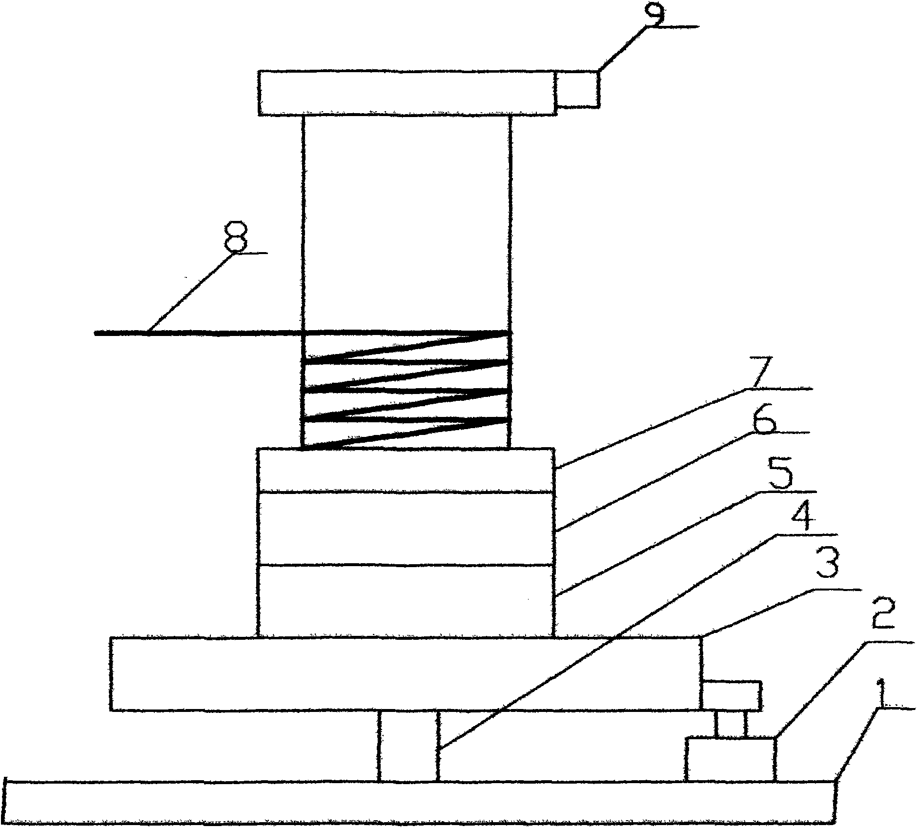
[0011] The embodiment of the present invention is like this, with reference to Figure 1 As shown, a kind of aircraft carrier catapult, the wheel 3 is installed on the body 1 through the shaft 4, the clutch 5, the speed reducer 6 are installed, the reel 7 is on the shaft 4, and one end of the steel cable 8 is installed on the reel 7, The other end of the steel cable 8 is connected to the aircraft hook, and the driver 2 drives the wheel 3. The outer diameter of the wheel 3 is greater than 1000mm, and the mass of the wheel ring is greater than 1000kg. good.

[0012] Working principle: the clutch 5 is in the disengaged state, and the brake 9 is released, so that one end of the steel cable 8 wrapped around the winch wheel 7 is pulled to the hook at the predetermined position of the aircraft by traction force, and the wheel disc 3 reaches the rated speed under the drive of the driver 2. That is, the take-off energy of the aircraft is 3 to 10 times, and the aircraft starts to meet ...


PUM

PropertyMeasurementUnit
Outer diameteraaaaaaaaaa

Abstract

The present invention relates to an aircraft carrier ejector with mechanical energy storage, which can store energy by turning a wheel disc at a high speed. The energy transmits to a decelerator through a clutch, and then transmits to a reel. A steel rope is connected with an airplane hook to eject the airplane. The invention has the advantages of high energy utilization rate, simple structure, convenient maintenance, and the driving power of the wheel disc driver of the invention is about 200 kilowatt.

Description

technical field [0001] The invention belongs to an aircraft catapult used on an aircraft carrier, in particular to a mechanical energy storage type catapult. technical background [0002] The ejection of an aircraft requires a lot of power. The steam catapult currently used has a complex structure, high energy consumption, and an energy utilization rate of about 6%. It consumes a lot of fresh water, has a high failure rate, and high maintenance costs. Although the steam catapult is improved, the above situation is still obvious. Contents of the invention [0003] The object of the present invention is to provide a kind of simple in structure, the utilization rate of energy is more than 1%, does not consume fresh water, and failure rate is low, the aircraft carrier launcher that maintenance cost is low. [0004] Technical solution of the present invention is as follows: [0005] 1. An aircraft carrier catapult comprises a driver, a brake, and a steel cable. Its technical ...

Claims


Application Information

Patent Timeline
IPC IPC(8): B64F1/06
Inventor 胡云
Owner 胡云
Why Eureka
Try Eureka