Check patentability & draft patents in minutes with Patsnap Eureka AI!

Damped stacking baffle

A damping and stacking technology, applied in the field of stackers, can solve the problems of poor thrust control, low work efficiency, uneven stacking of steel plates, etc. The effect of disassembly and maintenance

Inactive Publication Date: 2012-10-10
XIAMEN BAOGANG PRECISION STEEL MATERIALS TECH
View PDF2 Cites 0 Cited by
  • Summary
  • Abstract
  • Description
  • Claims
  • Application Information

AI Technical Summary

Problems solved by technology

During the production of the fixed bracket type stacking baffle, due to the impact of the steel plate (the stacked plate), the damage rate of the stacking baffle is high, the stacking of the steel plates is uneven, and the edge of the steel plate body is often damaged.
With the development needs of modern shearing lines, the above-mentioned stacking baffle method can only be used in occasions that generally require stacking quality and low speed
However, when continuous high-speed shearing and stacking of high-precision and high-quality plates (such as automobile "O5" plates and high-surface-quality home appliance plates) are required, high stacking speed, neat stacking, no edge damage, and no surface scratches are required. Injury and other quality requirements, the existing stacker equipment is difficult to meet
The main reason is that the stacking baffle of the stacker is not enough to absorb the impact force of the plate, the reverse thrust speed of the stacking baffle is slow, and the thrust control is not good.
At the same time, the cylinders used in the existing stacking baffles (components of the stacker) are ordinary cylinders. Although the thrust is large and the response speed is high during work, the compression displacement is small, and the impact load absorption and buffering capacity are very limited; although it has Certain damping and buffering effect, but no damping force adjustment function, can not achieve rapid release, low operating efficiency

Method used


Image

  • Damped stacking baffle
  • Damped stacking baffle

Examples


Embodiment Construction

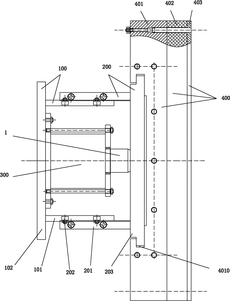
[0014] see figure 1 and 2 , the embodiment of the present invention is provided with a fixed bracket 100 , a movable bracket 200 , a double cylinder damping cylinder 300 and a baffle 400 . Fixed support 100 is fixed on the stacker ( figure 1 and 2 not shown in). The fixed bracket 100 is movably connected with the mobile bracket 200 through the guide rail 101 . The double cylinder damping cylinder 300 is fixed on the fixed bracket 100 , the piston rod 1 of the double cylinder damping cylinder 300 is in contact with the moving bracket 200 , and the baffle plate 400 is connected with the moving bracket 200 .

[0015] The fixed bracket 100 and the mobile bracket 200 are combined into a symmetrical rectangular frame structure, that is, the fixed bracket 100 is provided with four guide rails 101, and the guide rails 101 are vertically fixed on the seat plate 102, and the mobile bracket 200 is provided with clamping plates 203, 4 slide bars 201 equipped with pulleys 202, each sl...


PUM


Abstract

The invention discloses a damped stacking baffle and relates to a stacker. The damped stacking baffle is provided with a fixed bracket, a movable bracket, a damping cylinder and a baffle, wherein the movable bracket is movably connected with the fixed bracket through a guide rail; the damping cylinder is fixed on the fixed bracket; a piston rod of the damping cylinder is contacted with the movable bracket; and the baffle is connected with the movable bracket. The damped stacking baffle can automatically adjust damping force, adapts to impact force of plates in different specifications, prevents edges of the plates from being deformed or damaged, and makes the plates stacked regularly. A piston rod of the double-cylinder damping cylinder can be rapidly pushed out, so the stacking work efficiency is obviously improved, and the high-speed and high-quality continuous stacking work is realized. A titanium alloy plate of the clamping groove baffle has high strength and is hardly deformed or damaged; and a rubber plate can play a role in buffering when steel plates instantaneously impact on the stacking baffle, prevent a surface layer from being damaged, and guarantee that the edges of the stacked steel plates are hardly bent.

Description

technical field [0001] The invention relates to a stacker, in particular to a damping stacking baffle mainly used on the stacker of a continuous high-speed steel plate cross-cutting unit. Background technique [0002] The stacking baffle of the cross-cutting unit is one of the key equipment of the stacker. The current stacking baffle has various structures, including a fixed bracket type composed of a cylinder and a spring, a hinged bracket type stacking baffle and a simple anti-collision type. Baffles, etc., but most of the stackers use fixed-structure stacking baffles for production. During the production of fixed bracket type stacking baffles, due to the impact of steel plates (stacked plates), the damage rate of stacking baffles is high, the stacking of steel plates is uneven, and the edge of the steel plate body is often damaged. With the development needs of modern shearing lines, the above-mentioned stacking baffle method can only be used in occasions that generally ...

Claims


Application Information

Patent Timeline
Patent Type & Authority Patents(China)
IPC IPC(8): B65G57/00
Inventor 杨勤荣吴至夏柯根成袁焕何宗璟王怀闽黄磊姚万强
Owner XIAMEN BAOGANG PRECISION STEEL MATERIALS TECH
Features
  • R&D
  • Intellectual Property
  • Life Sciences
  • Materials
  • Tech Scout
  • Unparalleled Data Quality
  • Higher Quality Content
  • 60% Fewer Hallucinations
Learn More