Single row crossed roller bearing harmonic speed reducer

A technology of crossed roller bearing and harmonic reducer, applied in aerospace field

Inactive Publication Date: 2011-05-04
青岛创想机器人制造有限公司
View PDF4 Cites 13 Cited by
  • Summary
  • Abstract
  • Description
  • Claims
  • Application Information

AI Technical Summary

Problems solved by technology

[0002] Traditional harmonic reducers are usually like Figure 3 shows that there are many transmission shafts, using multiple pairs of deep groove ball bearings, the structure is complex, the volume and weight are large, and the bearing capacity is poor; or the manufacturing is complicated and the installation process is many, so its Very limited application

Method used


Image

  • Single row crossed roller bearing harmonic speed reducer
  • Single row crossed roller bearing harmonic speed reducer
  • Single row crossed roller bearing harmonic speed reducer

Examples


specific Embodiment approach

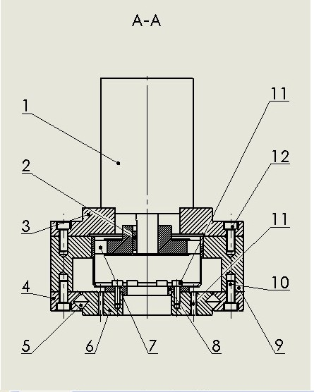
[0009] Specific implementation: The wave generator (7) is installed on the shaft of the motor (1), and the wave generator (7) is connected to the shaft of the motor (1) by a flat key (2), and the motor (1) is installed on the flange On (3), the flange (3) is connected to the rigid gear (9) through bolts (12), the rigid gear (9) is connected to the cross roller bearing outer ring (4) through bolts (10), and the flexible gear (8 ) is connected with the cross roller bearing inner ring (6) through bolts (11); the bearing roller (5) is installed between the cross roller bearing outer ring (4) and the cross roller bearing inner ring (6), and the flexible gear (8) Installed between the wave generator (7) and the rigid gear (9), the shaft of the motor (1) drives the wave generator (7) to rotate, and the flexible gear (8) meshes with the rigid gear (9). The tooth number difference between the flexible gear (8) and the rigid gear (9) is 2, resulting in a large reduction ratio; the flexi...


PUM


Abstract

The invention provides an original crossed roller bearing harmonic speed reducer. The speed reducer consists of a wave generator (7), wherein the wave generator (7) is arranged on a shaft of a motor (1), and is connected with the motor (1) by a flat key (2); the motor (1) is arranged on a flange plate (3) which is connected with a rigid gear (9) through a bolt (12); the rigid gear (9) is connected with a crossed roller bearing outer ring (4) through a bolt (10); a flexible gear (8) is connected with a crossed roller bearing inner ring (6) through a bolt (11); a bearing roller (5) is arranged between the crossed roller bearing outer ring (4) and the crossed roller bearing inner ring (6); and the flexible gear (8) is arranged between the wave generator (7) and the rigid gear (9); the shaft of the motor (1) drives the wave generator (7) to rotate, and the flexible gear (8) is engaged with the rigid gear (9); because the difference of teeth number of the flexible gear (8) and the rigid gear (9) is 2, a large reduction ratio is generated; and the flexible gear (8) is fixed on the crossed roller bearing inner ring (6), and the crossed roller bearing inner ring (6) rotates and outputs along with the flexible gear (8) to achieve the aim of reducing speed. The crossed roller bearing harmonic speed reducer has the advantages of compact structure, high accuracy, high bearing force, large reduction ratio, less return difference, small volume, light weight and the like.

Description

technical field [0001] The invention belongs to the fields of joints or rotating parts of industrial robots, rotating tables of precision machining centers, rotating parts of manipulators, medical equipment, measuring instruments, IC devices, aerospace and the like. It is a cross-roller bearing type harmonic reducer with the advantages of original compact structure, high precision, high bearing capacity, large reduction ratio, small hysteresis, small volume, and light weight. Background technique [0002] Traditional harmonic reducers are usually as image 3 As shown, there are many transmission shafts, many pairs of deep groove ball bearings are used, the structure is complex, the volume and weight are large, and the load-carrying capacity is poor; or the manufacture is complicated and the installation process is many, so its application is extremely limited. The invention has the particularity of compact structure and high precision can still be ensured under high rotating...

Claims


Application Information

Patent Timeline
Patent Type & Authority Applications(China)
IPC IPC(8): F16H1/04F16H57/02
Inventor 王桂林
Owner 青岛创想机器人制造有限公司
Why Eureka
Try Eureka