
Rapid vacuum induction casting electric furnace

A vacuum induction, melting and casting furnace technology, applied in furnaces, crucible furnaces, furnace components and other directions, can solve the problems of low production efficiency, difficult to accurately control the casting amount, low product quality, etc., to improve production efficiency, shorten melting and casting time, product quality high density effect

Inactive Publication Date: 2011-05-04
JINZHOU GUXING TECH
View PDF5 Cites 5 Cited by
  • Summary
  • Abstract
  • Description
  • Claims
  • Application Information

AI Technical Summary

Problems solved by technology

The problems of this kind of melting electric furnace are: 1. The mold needs to be heated to a suitable casting temperature before being put into the metal furnace shell. The middle mold will have a large heat loss, so the temperature of the mold will drop greatly after the raw materials are smelted into molten steel, resulting in a low yield when casting products with complex shapes, and the product pass rate can only reach 45%. High cost; 2. Because it is smelted first and then casted, it generally takes 90 minutes to cast a furnace of steel for smelting and casting, and the production efficiency is low; and because the crucible is manually controlled to turn over during casting, it is difficult to accurately control the casting amount, so the product density of casting Poor, low product quality

Method used


Image

  • Rapid vacuum induction casting electric furnace
  • Rapid vacuum induction casting electric furnace
  • Rapid vacuum induction casting electric furnace

Examples


Embodiment Construction

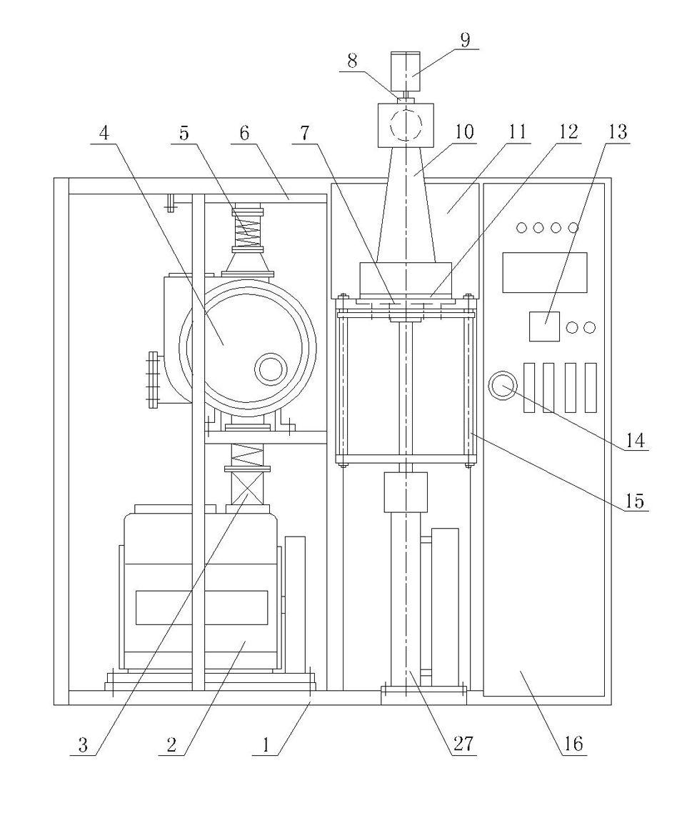
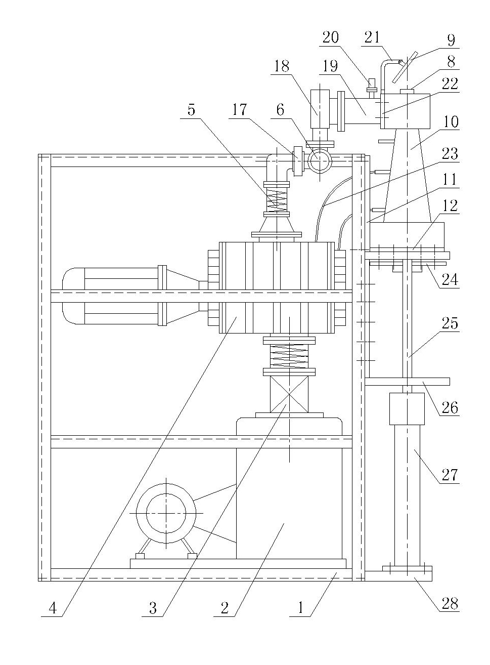
[0023] As shown in the figure, the vacuum induction rapid melting casting electric furnace has a frame 1, on which a vacuum system, a water cooling system 30, an intermediate frequency power supply 31 and a casting furnace 10 are arranged, and an air compressor is arranged behind the frame 1 29. Described vacuum system comprises the rotary vane vacuum pump 2 that connects successively through vacuum pipeline 19, Roots vacuum pump 4, vacuum filter 17, pre-vacuum storage tank 6 and the rectangular flange 22 that is connected with casting furnace 10, in rotary vane A vacuum differential valve 3 is provided between the vacuum pump 2 and the Roots vacuum pump 4, and a vacuum bellows 5 is respectively provided between the vacuum differential pressure valve 3 and the Roots vacuum pump 4 and between the Roots vacuum pump 4 and the vacuum filter 17. , on the vacuum pipeline 19 between the pre-vacuum storage tank 6 and the rectangular flange 22, a high vacuum valve 18, a vacuum inflatio...


PUM


Abstract

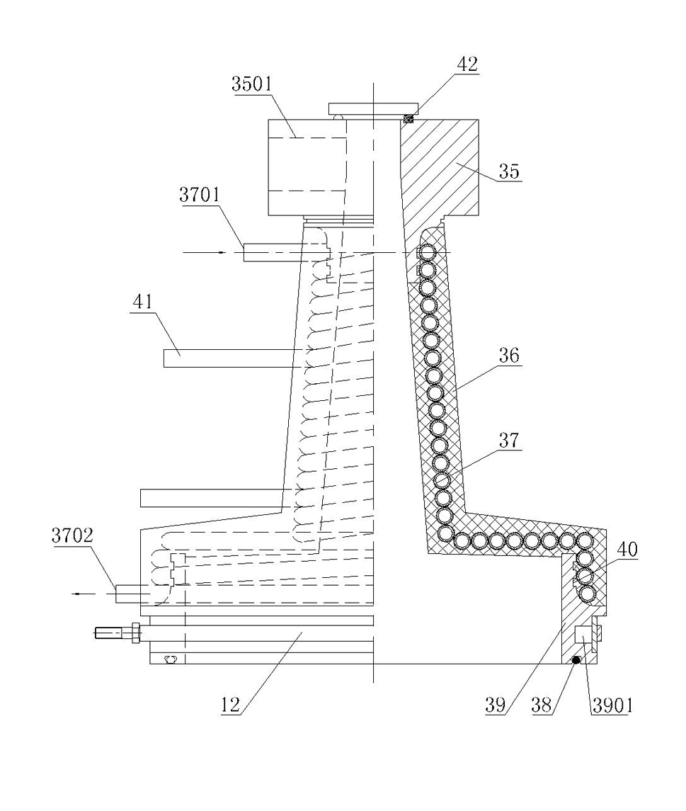
The invention discloses a rapid vacuum induction casting electric furnace comprising a rack, wherein a vacuumizing system, a water cooling system and a medium frequency power supply are arranged on the rack. The electric furnace is characterized in that the rack is provided with a casting furnace, wherein the casting furnace is composed of an inspection microscope base, a base, an insulated furnace tube and an inductor copper pipe which is helically preinstalled in the insulated furnace tube; the inspection microscope base is hermetically connected with a vacuum pipeline of the vacuumizing system; the inspection microscope base is provided with an inspection microscope; the two ends of the inductor copper pipe are provided with a water inlet and a water outlet respectively and are respectively led out via the insulated furnace tube; the section, corresponding to the middle part of the casting furnace, of the inductor copper pipe is electrically connected with the medium frequency power supply; a reciprocating hoisting mechanism is arranged below the casting furnace on the rack; and the upper end of the reciprocating hoisting mechanism is provided with a tray. The electric furnace has the following advantages: smelting and casting can be carried out simultaneously, the yield of cast products is high and the product percent of pass can reach more than 85%, so the electric furnace is especially applicable to casting products with complex shapes; the casting time is short and the production efficiency is high; and the product density is high and the product quality is good.

Description

technical field [0001] The invention belongs to melting and casting equipment, in particular to a vacuum induction rapid melting and casting electric furnace. Background technique [0002] The existing vacuum induction melting electric furnace is composed of a double-layer metal furnace shell, a crucible, an inductor and a mould, a vacuum system on one side of the metal furnace shell, and a vacuum system on the other side of the metal furnace shell. The rotating electrode and the intermediate frequency power supply connected with the rotating electrode are composed. The problems of this kind of melting electric furnace are: 1. The mold needs to be heated to a suitable casting temperature before being put into the metal furnace shell. The middle mold will have a large heat loss, so the temperature of the mold will drop greatly after the raw materials are smelted into molten steel, resulting in a low yield when casting products with complex shapes, and the product pass rate c...

Claims


Application Information

Patent Timeline
Patent Type & Authority Applications(China)
IPC IPC(8): F27B14/04F27B14/06F27B14/10F27B14/14F27D7/06
Inventor 赵志学张亚生刘伟曹晨光
Owner JINZHOU GUXING TECH
Learn More