Method for solving aerodynamic effect of long tunnel or tunnel group

A tunnel air and dynamic effect technology, applied in special data processing applications, instruments, electrical digital data processing, etc., can solve the problems of the insufficiency of the scale of the dynamic model experimental device, the increase of energy consumption, and the destruction of the car body structure.

Inactive Publication Date: 2011-05-04
CENT SOUTH UNIV
View PDF0 Cites 20 Cited by
  • Summary
  • Abstract
  • Description
  • Claims
  • Application Information

AI Technical Summary

Problems solved by technology

[0005] (2) Micro pressure wave noise pollutes the environment
[0006] (3) Air resistance increases, energy consumption increases, heat accumulation and temperature rise in the tunnel increase
The air resistance of a train running at high speed in a tunnel is greater than that of open-line running, both in terms of pressure difference resistance and frictional resistance, which not only increases the energy consumption of the train, but also leads to heat accumulation and temperature rise in the tunnel
[0007] (4) Damage to the tunnel structure and its internal facilities
The drastic change of air alternating pressure in the tunnel may damage the concrete lining structure in the tunnel and damage the lighting fixtures and other facilities inside the tunnel
[0008] (5) Destruction of the car body structure
[0013] 2. Unsteady incompressible flow model;
Finally, for the research on the aerodynamic effects of long tunnels and tunnel groups, it is too expensive to use actual vehicle tests, and it can only be carried out after the trains and tunnels are built; Aerodynamic requirements for large tunnels
Existing numerical calculation methods, such as numerical simulation calculations based on one-dimensional flow, cannot solve the micro-pressure wave at the tunnel entrance and the aerodynamic problems of tunnel groups; when solving three-dimensional flow, the computer capacity is difficult to meet the requirements, so it is necessary to find a Cost-effective numerical calculation method to solve it

Method used


Image

  • Method for solving aerodynamic effect of long tunnel or tunnel group
  • Method for solving aerodynamic effect of long tunnel or tunnel group
  • Method for solving aerodynamic effect of long tunnel or tunnel group

Examples


Embodiment Construction

[0049] In the one-dimensional calculation, the linear impedance + pore model is used to simulate the ballasted bed, and the basic equation of compression wave propagation for ballasted and ballasted bed effects in the tunnel is established, which is substituted into the mass addition item in the characteristic line equation for solution, thus The aerodynamic effect results of ballasted and ballastless tunnels are different.

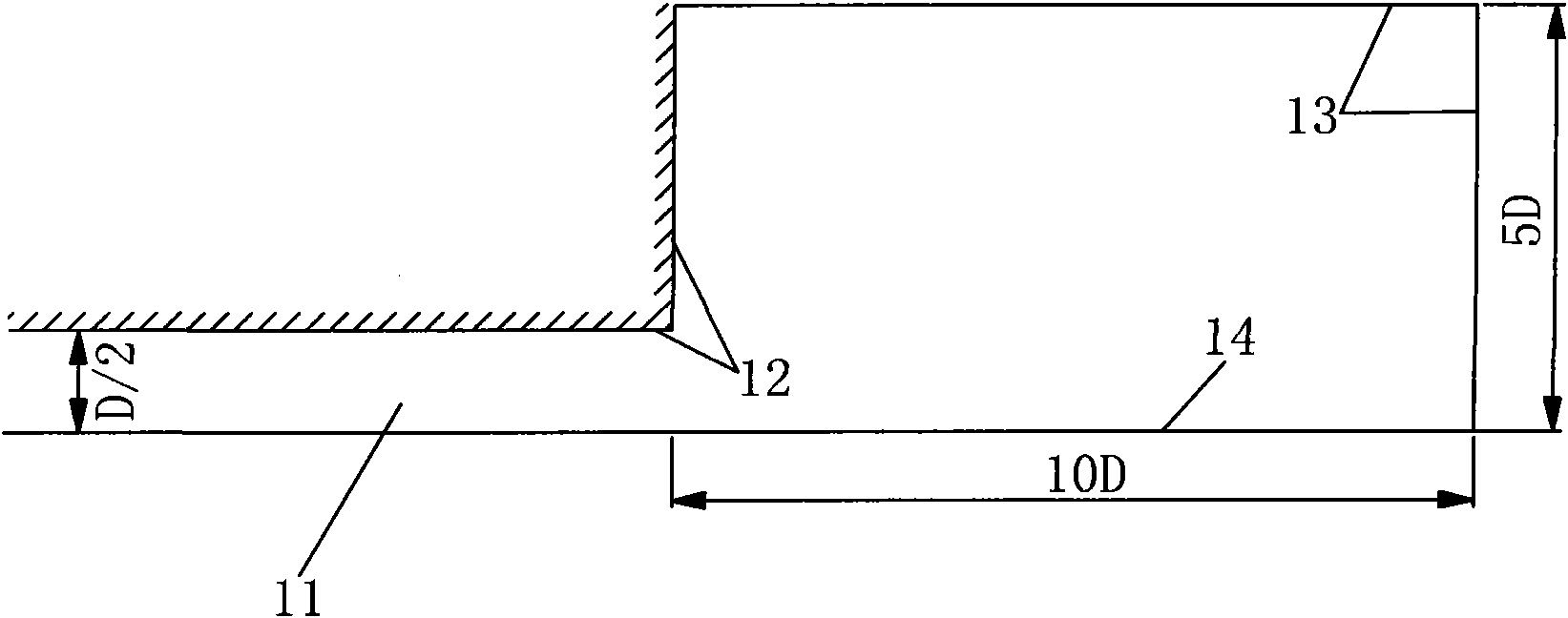
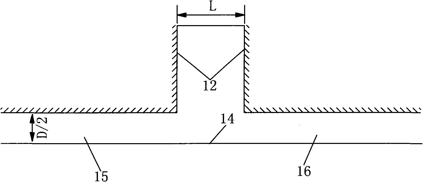
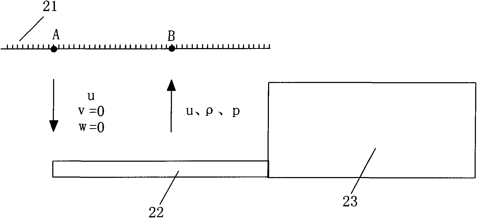
[0050] For the three-dimensional effect at the exit of the tunnel, the SIMPLE algorithm of the compressible flow field is used to solve the problem. A discrete governing equation based on the finite volume method is established in a three-dimensional arbitrary curvilinear coordinate system. The QUICK high-order scheme with upwind properties is added through delay correction technology, which can not only ensure the accuracy of the scheme, but also maintain the stability of the solution; For density processing, the density delay correction method is used t...


PUM


Abstract

The invention relates to a method for solving the aerodynamic effect of a long tunnel or a tunnel group. The method comprises the following steps: the method of one-dimensional characteristic is adopted to simulate the aerodynamic effect in a tunnel, a three-dimensional compressible SIMPLE algorithm is adopted to simulate the flow fields at the tunnel exit and between the two adjacent tunnels in the tunnel group; the results of the two algorithms are used for performing data exchange in a place in which the three-dimensional effect can be ignored far away from the tunnel exit, and the air pressure changes of the flow field in the tunnel and the micro-pressure wave at the tunnel exit can be simulated. The efficiency and precision of the calculation of the aerodynamic effect of the long tunnel or the tunnel group can be both considered; and when a high-speed train passes through a tunnel or two trains intersect in the tunnel, the air pressure change amplitude, micro-pressure wave and train wind in the tunnel can be solved.

Description

technical field [0001] The invention belongs to the technology of train tunnel aerodynamic effects and mitigation measures, and in particular relates to a three-dimensional / one-dimensional coupling calculation method for solving tunnel aerodynamic effects, which is especially suitable for long tunnels and tunnel group aerodynamic effects and mitigation measures. Background technique [0002] High-speed railway is the development direction of the world's railway passenger transport. However, with the increase of train speed, not only the air resistance of the train increases sharply and the energy consumption increases, but also a series of train aerodynamic forces that endanger driving safety, reduce passenger comfort and affect the surrounding environment have appeared due to the high-speed crossing of trains and passing through tunnels. question. [0003] The aerodynamic characteristics of a train running in a tunnel are significantly different from those of a train runni...

Claims


Application Information

Patent Timeline
Patent Type & Authority Applications(China)
IPC IPC(8): G06F17/50
CPCY02T90/00
Inventor 田红旗周丹鲁寨军杨明智熊小慧李志伟李燕飞
Owner CENT SOUTH UNIV
Why Eureka
Try Eureka