Fpd panel mounting device and mounting method thereof

An installation device and installation method technology, which are applied in the directions of cleaning methods and utensils, chemical instruments and methods, and cleaning methods using tools, etc., can solve the problem of easy generation of foreign objects, twill texture ridges consistent with the wiping direction, and can not completely eliminate wiping spots and other problems to achieve the effect of reducing the possibility of foreign matter

Inactive Publication Date: 2011-05-04
HITACHI HIGH-TECH CORP
View PDF9 Cites 0 Cited by
  • Summary
  • Abstract
  • Description
  • Claims
  • Application Information

AI Technical Summary

Problems solved by technology

[0010] However, if Image 6 As shown, from the schematic diagram of 2/2 twill twill weave, it can be seen that due to the periodicity of vertical and horizontal, the wiping spots cannot be completely eliminated at 0 degrees or 90 degrees
On the other hand, at 45 degrees, in the general 2/2 twill fabric, there is a problem that the ribs of the twill weave are consistent with the w

Method used


Image

  • Fpd panel mounting device and mounting method thereof
  • Fpd panel mounting device and mounting method thereof
  • Fpd panel mounting device and mounting method thereof

Examples


Embodiment Construction

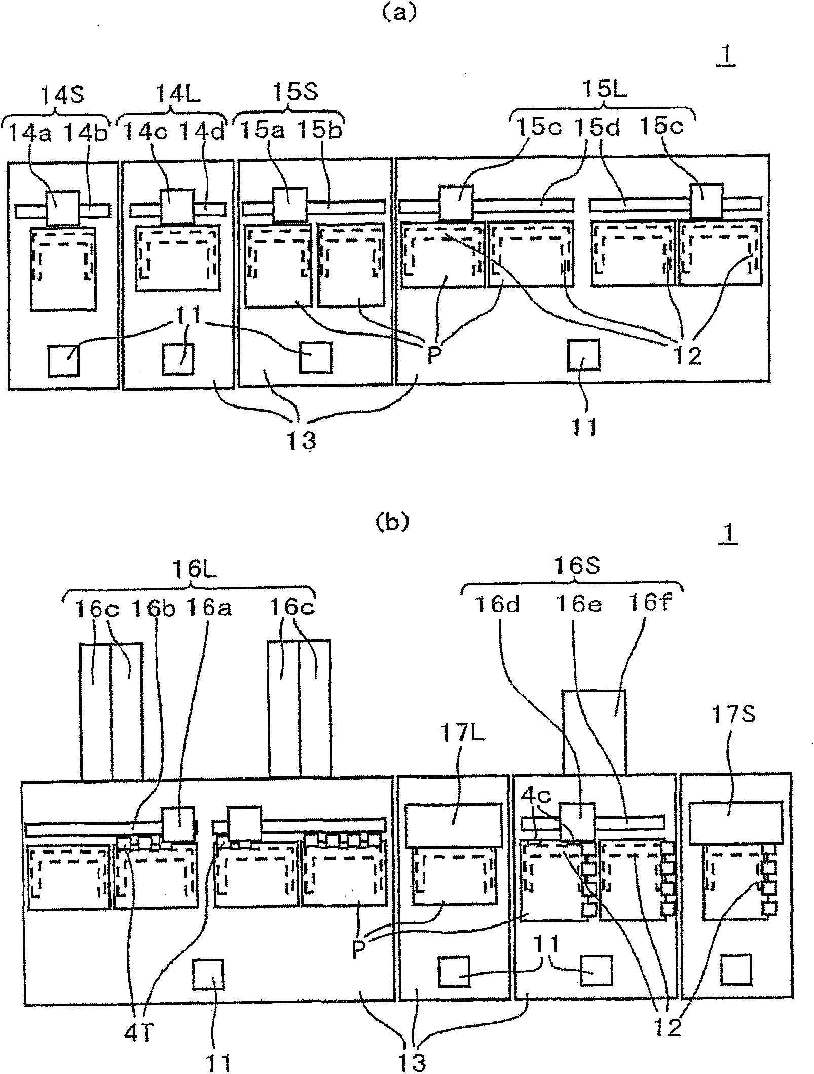
[0026] Next, use Figure 1 to Figure 7 One embodiment of the present invention will be described.

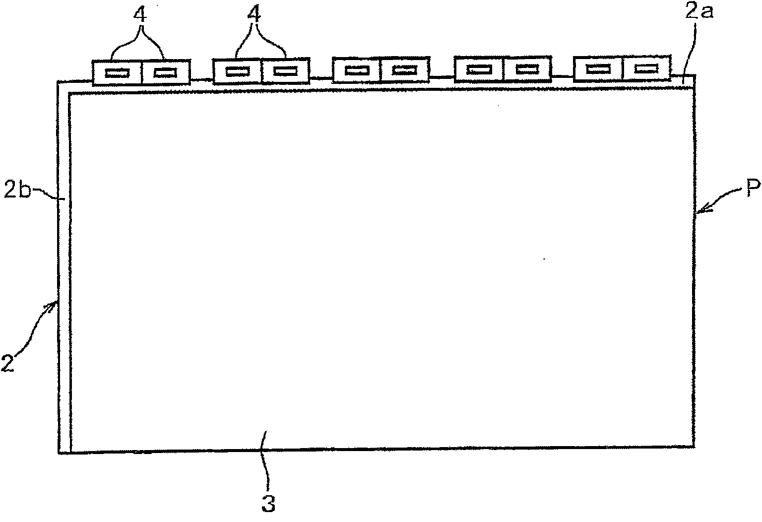
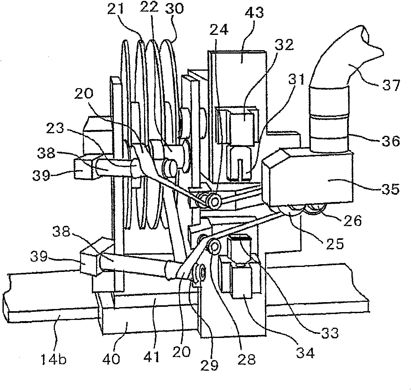
[0027] figure 1 It is a floor layout diagram showing the whole of the display substrate module assembly line 1 according to the embodiment of the present invention, figure 2 is a top view showing an example of a substrate being cleaned, image 3 It is a perspective view which shows the appearance of the terminal cleaning head which concerns on 1st Embodiment of this invention.

[0028] figure 1 The device is a transfer device consisting of a substrate holding mechanism 12 for holding a substrate P, and a transfer arm 11 for transferring the substrate to the position of the adjacent mounting device. The substrates are sequentially transferred from left to right in the figure. A production line device that performs various processing work on the peripheral portion of the substrate, and performs mounting and assembly of ICs or TABs, etc. figure 1 (a) means the first half, ...


PUM


Abstract

The present invention provides a technique, wherein the wiping performance of used cross grain fabric is sustained for improving the wiping performance in terminal cleaning of an FPD display substrate, and furthermore the longitudinal wire or cross wire that forms the ultra-thin fiber fabric of a cleaning strip does not cling on comb teeth shaped projections of a substrate terminal thereby preventing foreign matter. An FPD panel mounting device which is provided with a device which causes the relative movement of the cleaning strip and the substrate and causes the cleaning strip to slide and contact relatively to the substrate in a preset width for cleaning for cleaning is provided with the following components: an upper contact component which wipes a terminal part of substrate end that performs component mounting with the cleaning strip; and a lower contact component which wipes the back surface of the substrate end, wherein the cleaning strip is obliquely configured relatively to the substrate end.

Description

technical field [0001] The present invention relates to mounting a driver IC or a COF (Chip on Film: chip on film), FPC (Flexible Printed Circuit: flexible printed circuit) around the display substrate of a liquid crystal or plasma FPD (Flat Panel Display: flat panel display) board) and so-called TAB (Tape Automated Bonding: Tape Automated Bonding) connection and peripheral substrate (PCB, Printed Circuit Board: printed circuit board) mounting device and display substrate module assembly line composed of it. More specifically, for example, a mounting apparatus and mounting method having a substrate cleaning mechanism suitable for processing work for mounting TABs and ICs, and a display substrate module assembly line and display substrate module assembly method constituted according to the mounting apparatus and mounting method . Background technique [0002] The display substrate module assembly line is to sequentially carry out multi-step processing on the display substrat...

Claims


Application Information

Patent Timeline
IPC IPC(8): H05K13/00B08B1/00
Inventor 大录范行斧城淳
Owner HITACHI HIGH-TECH CORP
Why Eureka
Try Eureka