Method for cleaning combustion engine exhaust gases

A technology of internal combustion engine and exhaust gas, applied in the direction of internal combustion piston engine, separation method, combustion engine, etc., can solve the problem of increased pressure loss of filter exhaust gas, etc.

Active Publication Date: 2011-05-11
UMICORE AG & CO KG
View PDF3 Cites 10 Cited by
  • Summary
  • Abstract
  • Description
  • Claims
  • Application Information

AI Technical Summary

Problems solved by technology

In the case of catalytically coated wall-flow filter substrates, the shortfall in storage efficiency cannot be compensated solely by a linear increase in the amount of paint
This approach would result in an unacceptable increase in the exhaust pressure loss of the coated filter

Method used


Image

  • Method for cleaning combustion engine exhaust gases
  • Method for cleaning combustion engine exhaust gases
  • Method for cleaning combustion engine exhaust gases

Examples


example 1

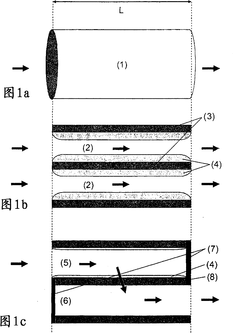
[0061] To produce the first filter PF1 according to the invention, first of all, 48 g / L of the above-mentioned paint suspension relative to the total volume of the wall-flow filter is introduced uniformly on the inflow side over the entire length of the wall-flow filter base body The wall between the inflow and outflow ducts. After drying and intermediate calcination, an additional 32 g / L (relative to the total length of the part) of paint suspension is introduced into the wall between the inflow and outflow ducts in the inflow side region, the length of which corresponds to the part 1 / 3 of the total length. This gets the corresponding image 3 A filter PF1 according to the invention comprising 80 g / L of the above-mentioned paint suspension.

example 2

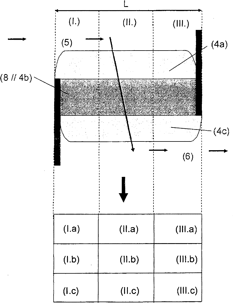
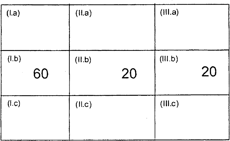
[0063] In order to produce the additional filter PF2 according to the invention, first of all, 68.8 g / L of the above-mentioned paint suspension relative to the total volume of the wall-flow filter is uniformly introduced on the inflow side between the inflow and outflow ducts in the area of ​​the inflow side The length of the inflow-side region corresponds to 2 / 3 of the total length of the wall-flow filter base body. After drying and intermediate calcination, an additional 11.2 g / L of coating suspension relative to the total volume of the wall-flow filter is applied as wall coating in the outflow conduit as an outflow-side region of a length of Corresponds to 1 / 3 of the total length of the part. This gets the corresponding Figure 8 A filter PF2 according to the invention comprising 80 g / L of the above-mentioned coating suspension.

[0064] The filters VPF, PF1 and PF2 produced as described were tested on an engine test bench with real exhaust gases of an engine operating wi...


PUM

PropertyMeasurementUnit
diameteraaaaaaaaaa

Abstract

Described is a method for cleaning the exhaust gases of internal combustion engines, which method is suitable for reducing harmful gases and particle emissions. Here, the exhaust gas to be cleaned is conducted, under operating conditions, with a discontinuous profile of the air ratio [lambda] across a wall-flow filter substrate which comprises a catalytically active coating containing one storage material. The storage material is suitable for temporarily storing one or more exhaust-gas components under certain operating conditions and releasing said exhaust-gas components again in a targeted fashion in the event of a suitable change in the operating conditions. The coating is configured such that the component has a gradient of the storage material concentration and/or of the total coating amount, with the highest concentration of the storage material in the longitudinal direction of the component being present on the inflow side. At least 60% by weight of the storage material in relation to its total amount is present in the walls between inflow and outflow ducts, and at least 50% by weight of the storage material in relation to its total amount is present in a first, inflow-side zone in the wall-flow filter substrate.

Description

technical field [0001] The invention relates to a method for cleaning the exhaust gases of an internal combustion engine using a material storing exhaust gas components and using a particle filter, which method is particularly suitable for use in motor vehicles. Background technique [0002] Exhaust gases from internal combustion engines in motor vehicles typically contain the harmful gases carbon monoxide (CO) and hydrocarbons (HC), nitrogen oxides (NOx) and possibly sulfur oxides (SOx), and also mainly carbon black residues and possibly Particles of adhered organic mass components. CO, HC and particulates are products of incomplete combustion of fuel in the engine's combustion chamber. If the combustion temperature locally exceeds 1000° C., nitrogen oxides are produced in the cylinder from nitrogen and oxygen in the intake air. Sulfur oxides are produced by the combustion of organic sulfur compounds which are always present in small amounts in non-synthetic fuels. In or...

Claims


Application Information

Patent Timeline
Patent Type & Authority Applications(China)
IPC IPC(8): B01D53/94B01D53/72B01D53/56B01D53/62B01D46/00F01N3/035
CPCB01D53/945B01D2255/9155F01N3/035F01N3/0814F01N2430/06F01N2510/06F01N2510/0682Y02T10/12
Inventor A·韦茨W·米勒M·沃特斯迈尔F·多恩豪斯M·勒施
Owner UMICORE AG & CO KG
Why Eureka
Try Eureka