

After-load blunt trailing edge wing profile designed based on sharp trailing edge wing profile
A technology of airfoil design and blunt trailing edge, which is applied in mechanical equipment, wind turbine components, wind power generation, etc., can solve the problem that the curvature distribution of the pressure surface cannot be effectively controlled, the excellent aerodynamic performance of the original airfoil is reduced, and the value range is not possible. Operability and other issues, to achieve the effect of increased post-loading performance, good lofting performance, and reliable theoretical support
- Summary
- Abstract
- Description
- Claims
- Application Information
AI Technical Summary
Problems solved by technology
Method used
Image


Examples
Embodiment 1
[0044] refer to figure 1 , is a comparison diagram of the original airfoil of NACA 63_215 and the rear-loaded blunt trailing edge airfoil of the present invention. The relative thickness of the original airfoil is 15%, which is widely used in the blade tip part of large wind turbines. According to the improvement scheme above, this embodiment takes the thickness of the blunt trailing edge is 3% of the maximum thickness of the airfoil, which is 0.45% of the chord length of the airfoil, and the rear airfoil camber equation of the original airfoil and a new camber equation obtained by the small deflection theory of concentrated loading on the trailing edge They are:
[0045]
[0046]
[0047] Contrasted with the camber curve of the airfoil profile after loading the blunt trailing edge of the present invention and the camber curve of the original airfoil , it can be seen that the airfoil of the present invention only properly fine-tunes the camber of the original a...
Embodiment 2
[0050] refer to Figure 4 , is the comparative figure of NACA 63_430 original airfoil and blunt trailing edge airfoil of the present invention. The relative thickness of the original airfoil is 30%, which is often used in the middle of the blades of large wind turbines. According to the improvement scheme above, this embodiment takes the thickness of the blunt trailing edge is 3% of the maximum thickness of the airfoil, which is 0.9% of the chord length of the airfoil, and the rear airfoil camber equation of the original airfoil and a new camber equation obtained by the small deflection theory of concentrated loading on the trailing edge They are:
[0051]
[0052]
[0053] The rear-loaded blunt trailing edge airfoil of the present invention comprises a leading edge 1, a suction surface 2, a front pressure surface 3, and a rear pressure surface (solid line) and blunt trailing edge5.
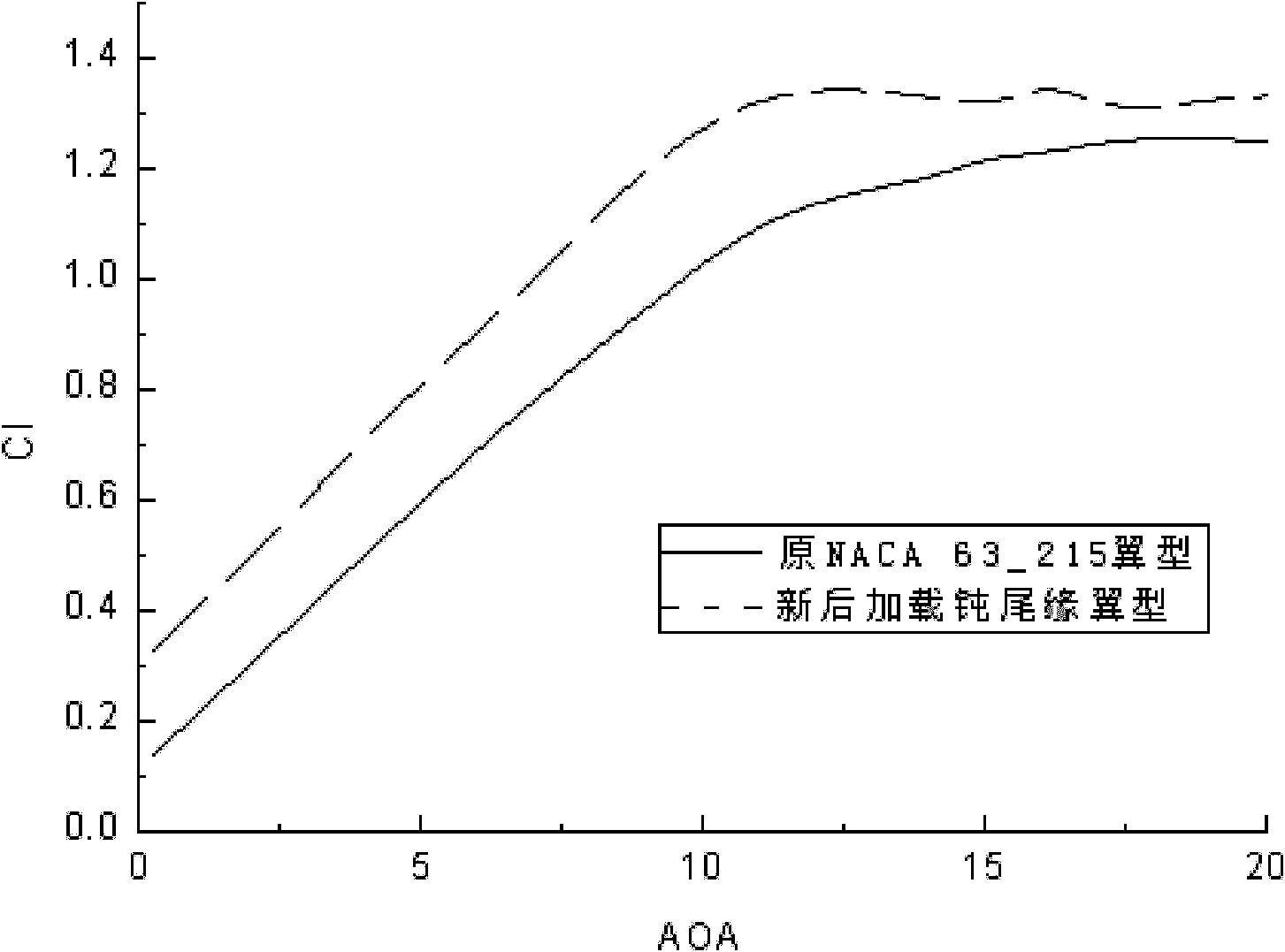
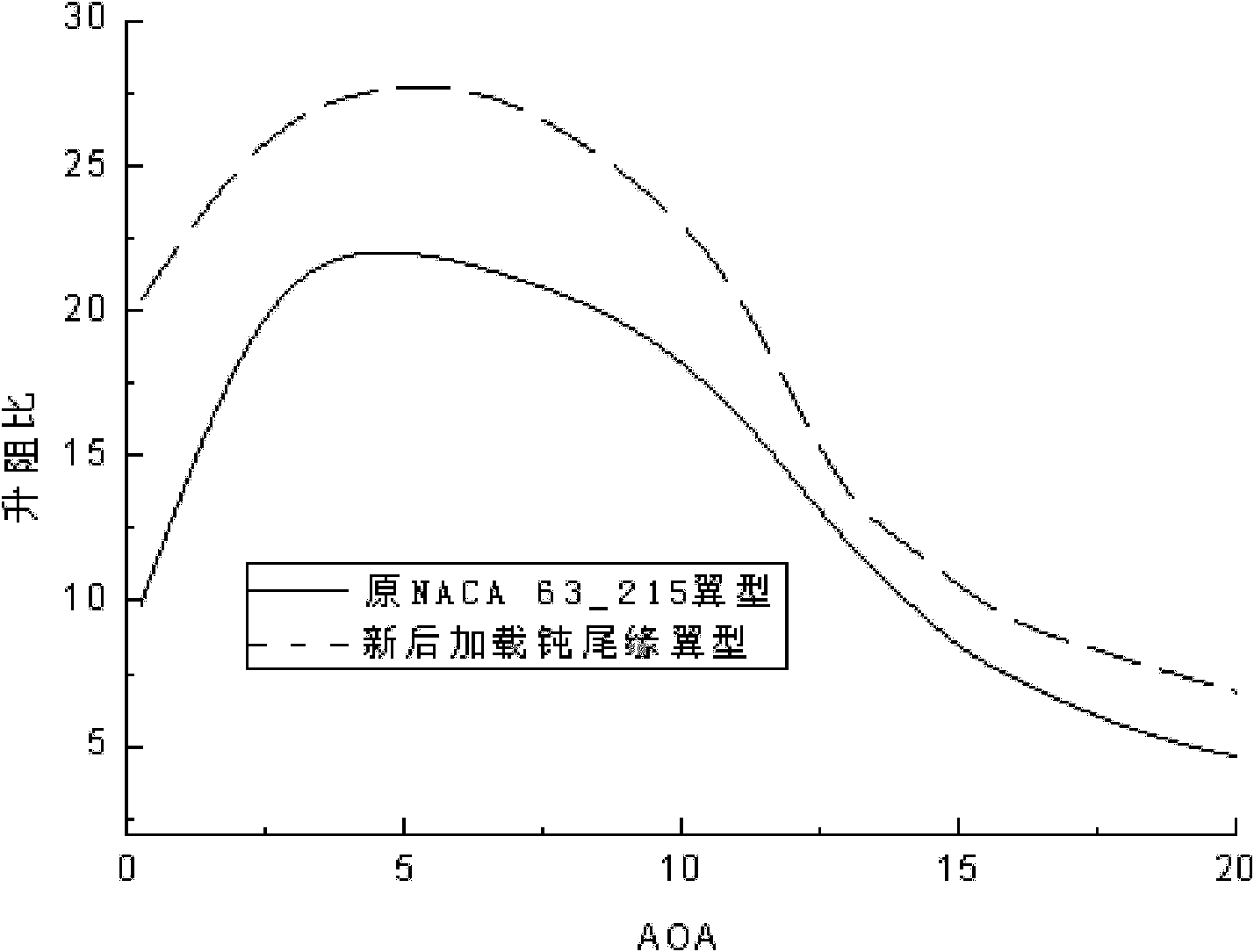
[0054] refer to Figure 5 and Figure 6 , the Reynolds number is , using ...
PUM
 Abstract
Description
Claims
Application Information