Condenser

A technology for condensers and condensing sections, applied in the field of built-in condensers, can solve problems such as the influence of heat transfer efficiency, and achieve the effects of improving the convective heat transfer coefficient in the tube, improving the cooling efficiency, and improving the radiation heat transfer coefficient

Inactive Publication Date: 2012-11-28
XI AN JIAOTONG UNIV
View PDF3 Cites 0 Cited by
  • Summary
  • Abstract
  • Description
  • Claims
  • Application Information

AI Technical Summary

Problems solved by technology

However, the channel size of this patent is more than 3mm, and the heat transfer process of the "line" contact of the built-in condenser has not been completely changed, and the heat transfer efficiency is affected to a certain extent.

Method used


Image

  • Condenser
  • Condenser
  • Condenser

Examples


Embodiment 1

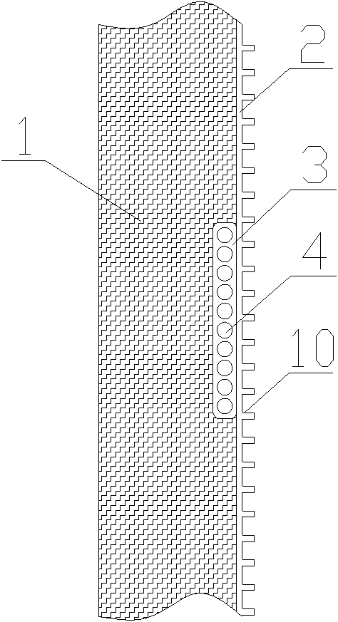
[0024] Embodiment 1: see figure 1 , 3. This embodiment includes a heat dissipation backplane 2 and a number of porous microchannel heat exchange flat tubes 3 that are closely attached to the inner side of the heat dissipation backplane 2 through thermal conductive silicone grease. The outer surface of the heat dissipation backplane 2 can be set to increase the heat exchange area The extended fins 10 of the present invention use heat-conducting silicone grease to reduce the contact thermal resistance, and the heat-insulating foam layer 1 presses several porous micro-channel heat-exchange flat tubes 3 to the inner side of the heat-dissipating backplane 2, and the porous micro-channel exchange There are several parallel passages 4 with circular cross-section, square cross-section or special-shaped cross-section along the same fluid flow direction in each of the hot flat tubes 3 with an equivalent diameter of 0.8-1.2 mm. In order to enhance heat exchange, the present invention can...

Embodiment 2

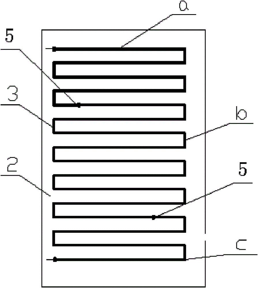
[0027] Example 2: see Figure 4 , this embodiment includes a heat dissipation backplane 2 and several porous microchannel heat exchange flat tubes 3 that are closely attached to the inner side of the heat dissipation backplane 2 through thermal conductive silicone grease. Pressed tightly to the inner side of the heat dissipation back plate 2, the porous microchannel heat exchange flat tubes 3 have several parallel tubes with a circular section, a square section or a special-shaped section with an equivalent diameter of 0.8-1.2mm along the same fluid flow direction. channel 4. The porous microchannel heat exchange flat tubes 3 constituting the superheated cooling section a, the two-phase cooling section b and the supercooled condensing section c of the condenser are arranged in parallel and horizontally, and each section is arranged on both sides of the porous microchannel heat exchange flat tubes 3 The distributing pipe 6 and the liquid collecting pipe 7 are connected, and th...

Embodiment 3

[0028] Example 3, see Figure 5In this embodiment, the porous microchannel heat exchange flat tubes 3 forming the superheated cooling section a, the two-phase condensing section b and the subcooled cooling section c of the condenser are vertically arranged in parallel. Other connections are the same as in Embodiment 2.

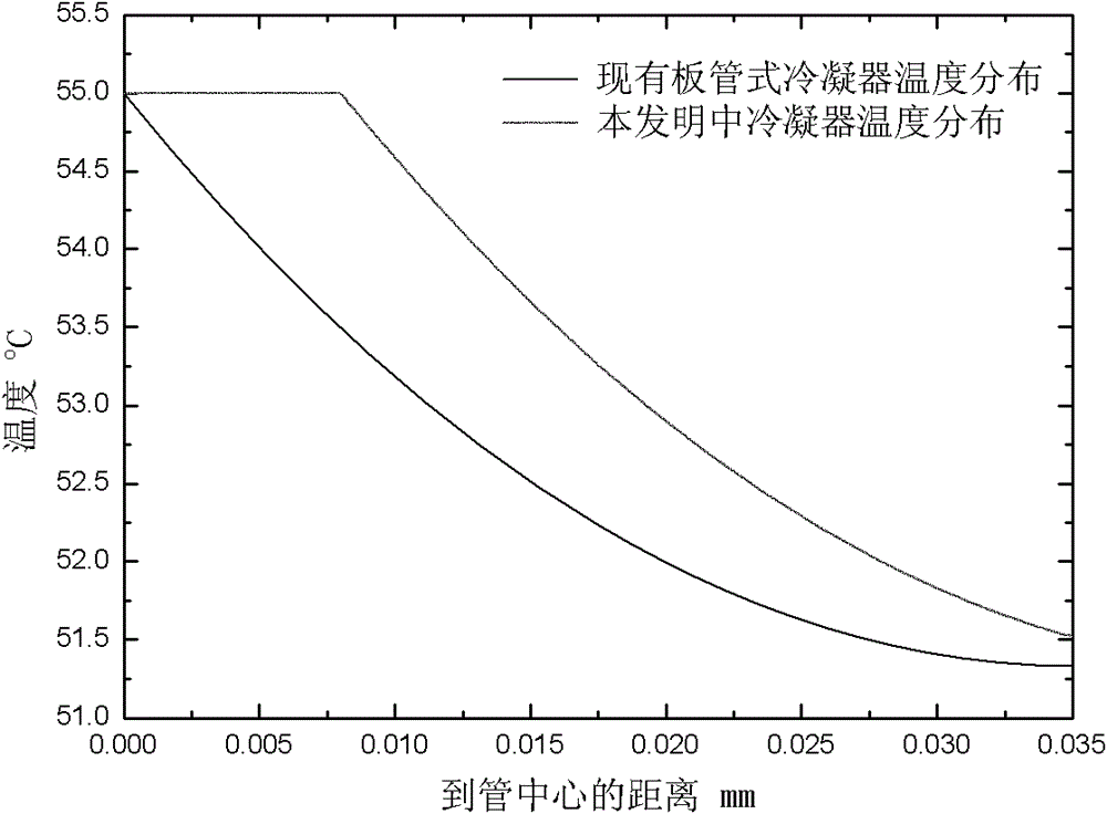
[0029] see Figure 4 , 5. The high-temperature and high-pressure refrigerant vapor from the compressor first enters the distribution pipe 6, enters the multi-hole microchannel flat tube condenser 3 under the action of the baffle plate 8, and then enters the liquid collection pipe 7. Since the refrigerant is superheated steam at this time , the specific volume is large, so more porous microchannel flat tubes are used. The tubes are arranged in parallel to ensure that the refrigerant has a sufficient flow velocity in the porous microchannel flat tube. After condensing to saturated liquid, the specific volume of the refrigerant is greatly reduced. At this time,...


PUM


Abstract

The invention discloses a condenser which is composed of a porous micro through heat exchange flat tube, a corresponding connecting header and a heat dissipation back plate arranged at one side of the heat exchange flat tube. In the invention, the structure is compact, the heat exchange efficiency is high, the aluminum flat tube is adopted, thus the condenser is more advantageous than the existing copper heat exchange tube in the aspect of economical efficiency, and the condenser is suitable for the fields such as refrigeration, chemical engineering, energy source, heat exchange and the like.The condenser is characterized in that on the one hand, since the porous micro channel flat tube structure is adopted, the coefficient of heat transfer in the tube is improved, and simultaneously theflow resistance of a refrigerant in the tube is reduced; and on the other hand, the contact type of the condenser and the side wall of the heat dissipation back plate is surface contact, so that contact thermal resistance is reduced, the average temperature of the side wall of the heat dissipation back plate is improved, and the heat exchange between the side wall of the back plate and the ambient air is strengthened, namely the condensing effect is strengthened, thus, when the lengths of pipes are the same, the quantity of the condenser can be increased, or when the heat exchange quantities are the same, the length of the pipes can be reduced, therefore the condenser is more compact, simultaneously the material consumption is reduced, and the condenser has a certain advantage in the aspect of economical efficiency.

Description

technical field [0001] The invention belongs to the field of general household refrigeration, and in particular relates to a built-in condenser suitable for refrigeration equipment such as general refrigerators or freezers. Background technique [0002] Refrigerators and freezers are the only household electrical appliances that consume electricity throughout the day. While bringing people a comfortable life, they also consume a lot of electricity. The promulgation of my country's "Restricted Values ​​of Power Consumption and Energy Efficiency Levels of Household Refrigerators (GB12021.2-2008)" has mandated technological transformation and innovation on refrigerators, hoping to save more energy. From the point of view of the refrigeration system, the condenser undertakes the task of radiating heat outward, and its heat load is the largest, so it is one of the main components that need to be strengthened in energy-saving research. Existing refrigerator condensers are mainly ...

Claims


Application Information

Patent Timeline
Patent Type & Authority Patents(China)
IPC IPC(8): F25B39/04
CPCF25B40/02F25B39/04F25B40/04F28F2270/00F28F1/022
Inventor 刘迎文刘冈云童欢徐升华胡露露
Owner XI AN JIAOTONG UNIV
Why Eureka
Try Eureka