
Method for measuring response time of photoelectric measurement instrument

A technology for photoelectric measurement and instrument response, which is applied to methods, instruments, and optical performance tests that are compared with reference electrical parameters. , the effect of ensuring integrity

Inactive Publication Date: 2011-05-11
THE 41ST INST OF CHINA ELECTRONICS TECH GRP
View PDF0 Cites 8 Cited by
  • Summary
  • Abstract
  • Description
  • Claims
  • Application Information

AI Technical Summary

Problems solved by technology

However, due to its special performance, the output results of photoelectric measuring instruments are not suitable for response time measurement.
The current technology for measuring the response time is to use the acousto-optic modulator as an optical switch to measure the response time of the detector, but it is only suitable for the response time measurement of the detector element level, and it is inconvenient to be flexibly used for the response time measurement of the instrument

Method used


Image

  • Method for measuring response time of photoelectric measurement instrument
  • Method for measuring response time of photoelectric measurement instrument
  • Method for measuring response time of photoelectric measurement instrument

Examples


Embodiment Construction

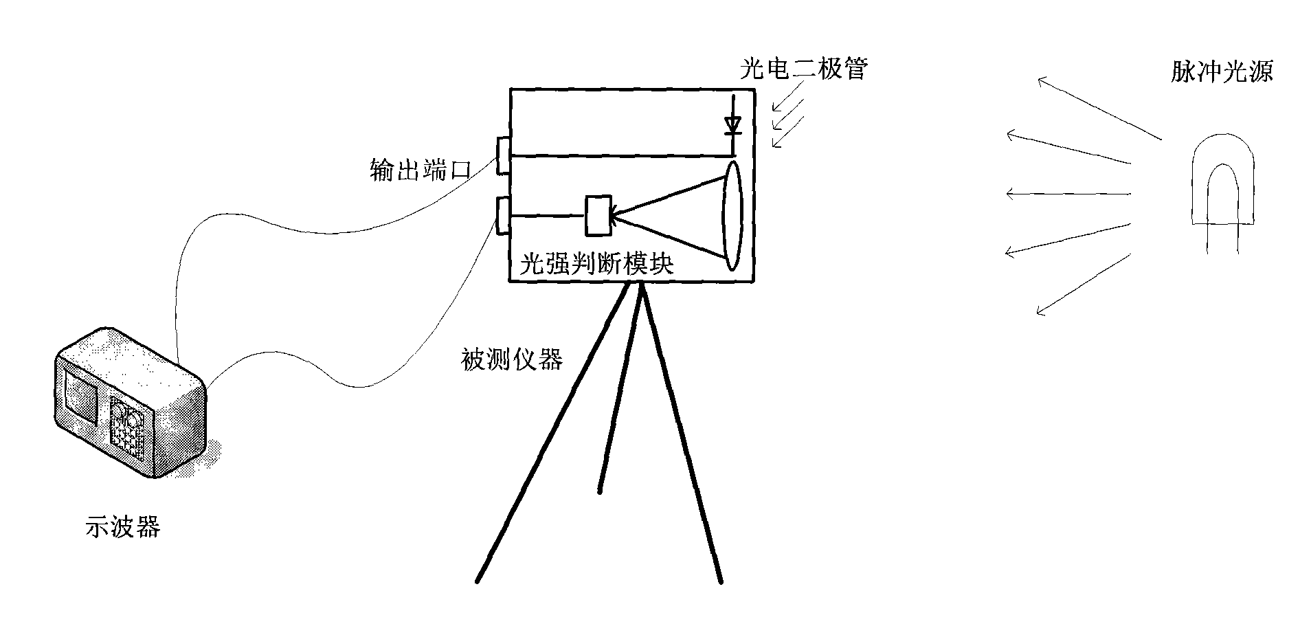
[0010] combine figure 1 , the measuring method of photoelectric measuring instrument response time of the present invention, comprises the following steps:

[0011] 1.1 Photoelectric measuring instruments are generally composed of incident optical system, photoelectric detector, signal processing circuit, input and output module, external interface and other parts. The incident optical system receives external light radiation and converges it on the target surface of the detector. The signal is converted into an electrical signal, and the signal processing circuit further processes the electrical signal, and displays the analysis result, and the external interface is used to output measurement information.

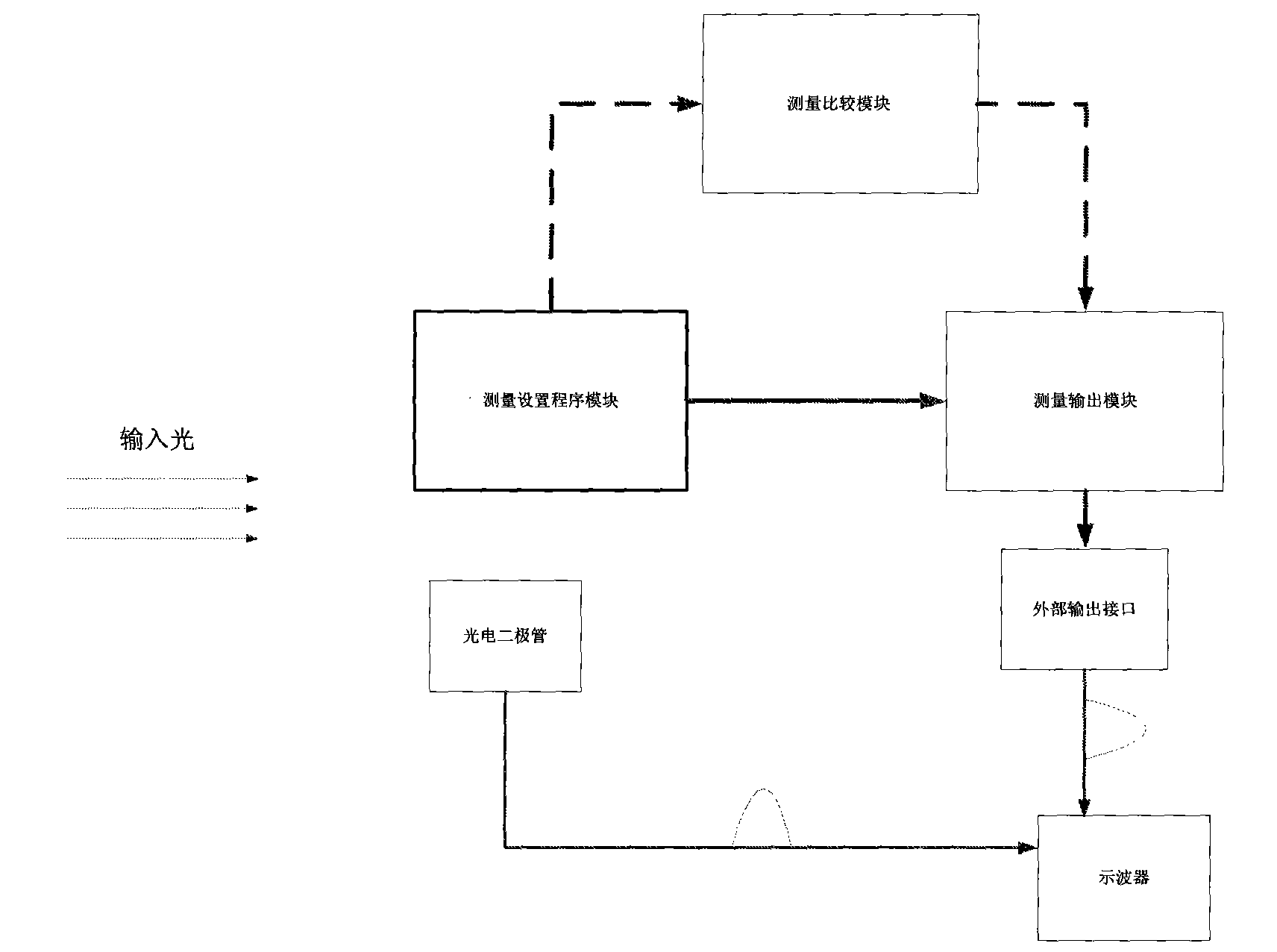
[0012] 1.2 The present invention proposes to use the internal software and hardware resources of the photoelectric measuring instrument to embed a response time measurement function module. The functional module includes a photodiode and its signal processing circuit, a l...


PUM


Abstract

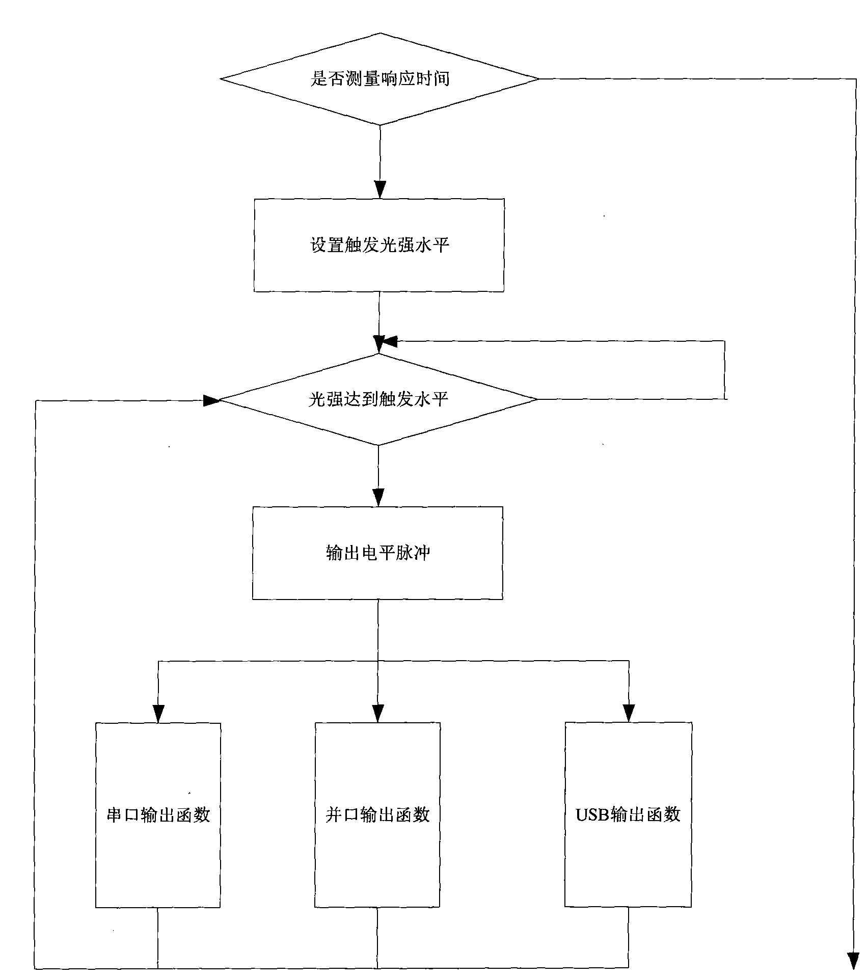
The invention discloses a method for measuring response time of a photoelectric measurement instrument, comprising the steps of: firstly, modulating a light source to obtain intense pulsed light used for measurement, and selecting modulating pulse width according to the characteristic difference of a measurement instrument; setting the measurement instrument into a response time measurement mode, and starting to measure; when light intensity to be measured reaches a trigger level, outputting a single level pulse to an oscilloscope by the measurement instrument, outputting a pulse by a photoelectric diode to the oscilloscope, and measuring the time difference of the two paths of pulses, wherein the time difference can be used as the response time of the photoelectric measurement instrument. In the invention, the measurement response time of the instrument is obtained by comparing the level pulse output by the photoelectric measurement instrument with the reference pulse output by the photoelectric diode, and the advantages of convenience, rapidness and high precision are achieved.

Description

technical field [0001] The invention belongs to the field of photoelectric testing, in particular to a method for measuring the response time of a photoelectric measuring instrument. Background technique [0002] In the field of photoelectric testing, photoelectric measuring instruments receive light radiation, convert light intensity signals into electrical signals through detectors, and further process and output them. Response time is an important parameter to describe the response speed of photodetectors to incident radiation. It needs to be considered first in the case of modulated optical signals and fast optical pulse measurements. It is directly related to the correctness of instrument measurement results and is a very important technical indicator of measuring instruments. However, due to the special performance of the photoelectric measuring instrument, the output result is not suitable for response time measurement. The current technology for measuring the respon...

Claims


Application Information

Patent Timeline
IPC IPC(8): G01M11/02G01D5/34G01J1/10G01J11/00
Inventor 朱文星孙守军
Owner THE 41ST INST OF CHINA ELECTRONICS TECH GRP
Learn More