
Antenna device

An antenna device and antenna technology, which is applied to antenna grounding devices, antennas, resonant antennas, etc., can solve the problems of large radiation resistance of dipole antennas, difficult market acceptance of dual antenna ends, and low input impedance.

Inactive Publication Date: 2011-05-11
LINK TECH INC
View PDF2 Cites 3 Cited by
  • Summary
  • Abstract
  • Description
  • Claims
  • Application Information

AI Technical Summary

Problems solved by technology

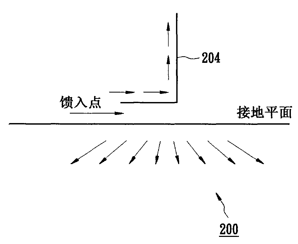
[0006] However, the conventional monopole antenna device applied to the USB inherits the inherent disadvantages of the general monopole antenna structure, that is, the monopole antenna structure has lower input impedance compared to the dipole antenna structure, and the dipole antenna structure The radiation resistance of the monopole antenna is larger than that of the monopole antenna, so the efficiency of the monopole antenna is poor
On the other hand, if a dipole antenna structure is used in a miniaturized wireless communication device, the extra volume brought by the dual antenna ends of the dipole antenna structure will not be easily accepted by the market under the demand of consumers who emphasize lightness, lightness and shortness.

Method used


Image

  • Antenna device
  • Antenna device
  • Antenna device

Examples


Embodiment Construction

[0043] The invention discussed herein is an antenna device. In order that the present invention can be thoroughly understood, the detailed composition will be set forth in the following description. It is evident that the practice of the invention is not restricted to specific details well known to those skilled in the art. On the other hand, well-known compositions have not been described in detail in order not to unnecessarily limit the invention. The preferred embodiments of the present invention will be described in detail as follows, but except these detailed descriptions, the present invention can also be widely implemented in other embodiments, and the scope of the present invention is not limited, it is based on the claims of the present invention allow.

[0044] Figure 5 A side view of an antenna device according to an embodiment of the present invention is shown. Such as Figure 5 As shown, the antenna device 500 includes a printed circuit board 502 , an antenn...


PUM


Abstract

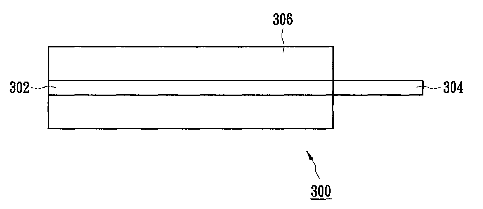
The invention discloses an antenna device, which comprises a planar monopolar antenna device and an extension layer. The planar monopolar antenna device is provided with an electromagnetic shielding box. The extension layer is made of conductive material and extends outwards from an antenna feed-in point of the electromagnetic shielding box of the planar monopolar antenna device.

Description

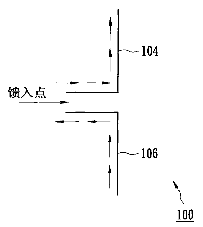
technical field [0001] The invention relates to an antenna device, in particular to an antenna device with an electromagnetic shielding box. Background technique [0002] In a wireless communication system, an antenna device is required to transmit and receive electromagnetic waves carrying signals. A basic antenna architecture, the dipole antenna architecture, originated as an invention in the 19th century. figure 1 A schematic diagram showing the architecture of a dipole antenna. Such as figure 1 As shown, the dipole antenna 100 respectively has two antenna ends extending outward from an antenna feeding point. Wherein, a first antenna terminal 104 serves as a live wire of the dipole antenna 100 , and a second antenna terminal 106 serves as a ground wire of the dipole antenna 100 . figure 1 The current direction of the antenna terminals 104 and 106 is displayed, and the current value at the antenna feeding point is maximum, while the current value at both ends of the an...

Claims


Application Information

Patent Timeline
IPC IPC(8): H01Q1/00H01Q1/48H01Q9/04
Inventor 林峻仪陈信锠
Owner LINK TECH INC
Learn More