

Electrolytic phosphating method for steel wires
An electrolytic phosphating and steel wire technology, applied in phosphating and other directions, can solve the problems of environmental pollution, affecting production efficiency and product quality, and high energy consumption
- Summary
- Abstract
- Description
- Claims
- Application Information
AI Technical Summary
Problems solved by technology
Method used
Image

Examples
Embodiment 1
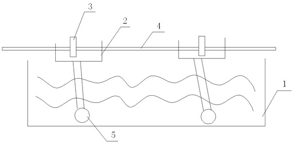
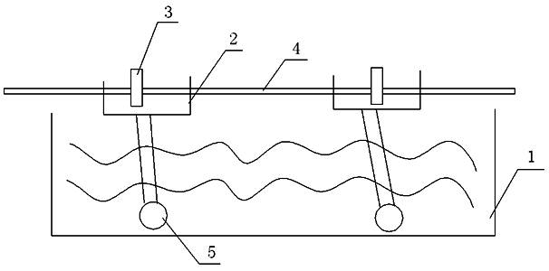
[0011] The invention provides a method for electrolytic phosphating of a steel wire, the steps of which are:
[0012] Step 1. Remove the oxide skin on the surface of the steel wire after heat treatment, and then rinse at room temperature. After rinsing the steel wire, perform surface activation treatment on the surface of the steel wire. Surface activation treatment refers to immersing the steel wire in a surface regulator solution with a concentration of 8%. , the immersion time is 5 seconds, the surface conditioner is emulsifier OP-10, and then more crystal nuclei are formed on the surface of the steel wire, the steps are:
[0013] Step 2. Let the activated steel wire pass through the electrolytic phosphating cell with an anode. During the passage, the steel wire cannot contact the anode. The passing speed depends on the thickness of the steel wire. The thicker the steel wire, the slower the passing speed The current passing through the anode is adjusted according to the req...
Embodiment 2
[0017] The invention provides a method for electrolytic phosphating of a steel wire, the steps of which are:
[0018] Step 1. Remove the oxide skin on the surface of the steel wire after heat treatment, and then wash it at room temperature. After the steel wire is rinsed, perform surface activation treatment on the surface of the steel wire. Surface activation treatment refers to immersing the steel wire in a surface adjustment solution with a concentration of 9%. , the immersion time is 3 seconds, and the surface regulator is emulsifier OP-10;
[0019] Step 2. Let the activated steel wire pass through the electrolytic phosphating cell with an anode. During the passage, the steel wire cannot contact the anode. The passing speed depends on the thickness of the steel wire. The thicker the steel wire, the slower the passing speed The current passing through the anode is adjusted according to the required thickness of the phosphorus layer of the steel wire and the diameter of ...
Embodiment 3
[0022] The invention provides a method for electrolytic phosphating of a steel wire, the steps of which are:
[0023] Step 1. Remove the oxide skin on the surface of the steel wire after heat treatment, then wash it at room temperature. After the steel wire is rinsed, perform surface activation treatment on the surface of the steel wire. Surface activation treatment refers to immersing the steel wire in a surface regulator solution with a concentration of 8%. , the immersion time is 5 seconds, and the surface conditioner is emulsifier OP-10;
[0024] Step 2. Let the activated steel wire pass through the electrolytic phosphating pool with an anode. During the passage, the steel wire cannot contact the anode. The passing speed depends on the thickness of the steel wire. The thicker the steel wire, the slower the passing speed , the current passing through the anode is adjusted according to the required thickness of the phosphorus layer of the steel wire and the diameter of the s...
PUM
 Abstract
Description
Claims
Application Information