Joint drainage type cement concrete road structure and construction method thereof

A cement concrete and pavement structure technology, applied in the direction of roads, roads, pavement details, etc., can solve the problems of long time required, narrow joints, aging, etc., and achieve the effect of improving service life, simple pavement structure, and strengthening connection.

Inactive Publication Date: 2011-05-18
CHANGSHA UNIVERSITY OF SCIENCE AND TECHNOLOGY
View PDF5 Cites 5 Cited by
  • Summary
  • Abstract
  • Description
  • Claims
  • Application Information

AI Technical Summary

Problems solved by technology

[0003] For the problem of joints that are prone to water seepage, sealing materials are usually used to seal the joints to prevent water from seeping down through the joints. Under the combined effects of moisture, humidity and driving load, repeated complex effects such as stretching, compression, shearing, etc., are prone to damage such as extrusion, debonding, aging, falling off, etc., and soon lose the waterproof effect of sealing seams
The current various sealing materials (including commonly used asphalt, and various special sealing materials specially developed) have the problems of poor durability and unsatisfactory use effect
If it cannot be maintained and replaced in time, rain and snow will seep into the joints, which will accelerate the destruction of the pavement structure, reduce the performance and service life of the pavement, and increase the maintenance workload.
Since the treatment of cement concrete pavement diseases such as grouting, hollowing out, and broken boards is relatively complicated and takes a long time, once damage occurs, it will have a great impact on traffic

Method used


Image

  • Joint drainage type cement concrete road structure and construction method thereof
  • Joint drainage type cement concrete road structure and construction method thereof
  • Joint drainage type cement concrete road structure and construction method thereof

Examples


Embodiment Construction

[0020] The present invention will be further described below in conjunction with the accompanying drawings and specific embodiments.

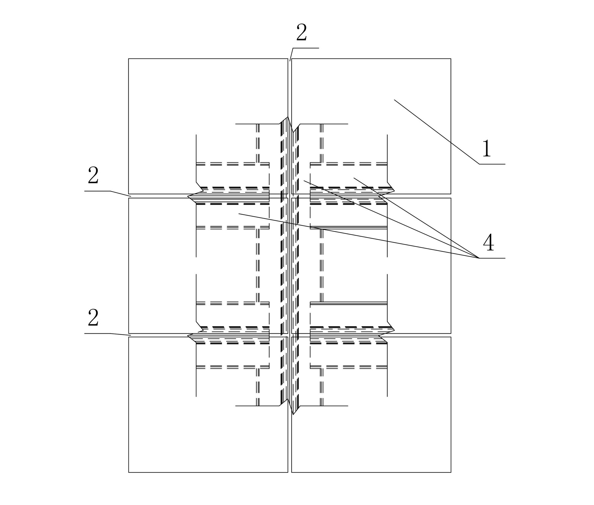
[0021] a kind of like figure 1 The joint drainage type cement concrete pavement structure of the present invention shown is that the cement concrete pavement structure is composed of a plurality of cement concrete slabs 1 spliced ​​together, and crisscross joints 2 are left between each cement concrete slab 1. The bottom of 1 and corresponding to the bottom of each joint 2 is provided with a groove-like water-collecting aluminum plate 4 leading to the drainage system 3 at the edge of the road surface.

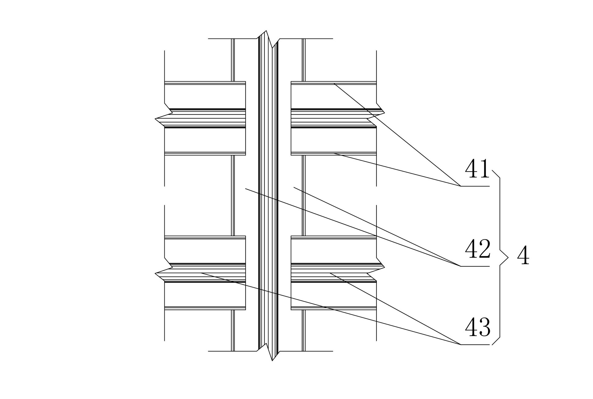
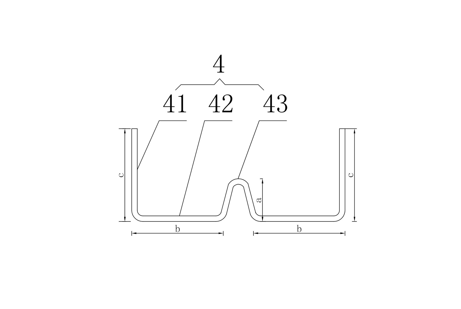
[0022] In this embodiment, the groove-like water-collecting aluminum plate 4 specifically refers to image 3 The cross-section shown is a water-collecting aluminum plate 4 that resembles a "W" shape. The water-collecting aluminum plate 4 includes two wings 41 extending to the outer edges of both sides, two grooves 42 connected to the bottom en...


PUM


Abstract

The invention discloses a joint drainage type cement concrete road structure. The cement concrete road structure is formed by splicing a plurality of cement concrete slabs; vertically and horizontally staggered joints are retained among all the cement concrete slabs; and a water collecting aluminum plate which is similar to a groove shape and leads to an edge drainage system is arranged at the bottom of the cement concrete road structure and below all the joints. A construction method of the road structure comprises the following steps of: designing concrete positions of the joints at the construction planning road section; then placing and fixing the water collecting aluminum plate on a road base layer in the corresponding position; constructing on the road base layer paved with the water collecting aluminum plate according to the conventional process to obtain a road structure body; then sawing at the joint positions; and finally, constructing the edge drainage system. The cement concrete road structure of the invention has the advantages of simple structure, convenience of construction, high durability, and the like.

Description

technical field [0001] The invention relates to a concrete pavement and a construction method thereof, in particular to a drainable concrete pavement and a construction method thereof. Background technique [0002] In order to avoid irregular cracking of the poured cement concrete pavement due to drying and temperature shrinkage, the new cement concrete pavement must be divided into regular plates with a certain size by longitudinal and transverse joints. The existence of joints makes it easy for rain and snow water to penetrate into the interior of the pavement structure through the joints, softening the pavement material, and under the repeated action of the traffic load, it will generate slurry, which will make the bottom of the slab hollow, and then cause the slab to break and accelerate the destruction of the pavement structure . Slurry, void at the bottom of the slab, broken slab, etc. are the most common diseases in cement concrete pavement. [0003] For the problem...

Claims


Application Information

Patent Timeline
IPC IPC(8): E01C11/04E01C11/24E01C11/22
Inventor 田小革
Owner CHANGSHA UNIVERSITY OF SCIENCE AND TECHNOLOGY
Why Eureka
Try Eureka