
Energy-saving furnace with secondary combustion structure

A secondary combustion and energy-saving furnace technology, which is applied to household cooking utensils, heating fuels, household appliances, etc., can solve the problems of low gas utilization rate, uneven heating of pots and utensils, and insufficient dispersion of firepower distribution, so as to achieve full combustion and energy saving better effect

Inactive Publication Date: 2011-05-18
曾文洲
View PDF9 Cites 5 Cited by
  • Summary
  • Abstract
  • Description
  • Claims
  • Application Information

AI Technical Summary

Problems solved by technology

[0002] Gas stoves are widely used in many places. Compared with conventional gas stoves, the application number provided by the applicant is 201010241872.9, and the name is the boiler chamber combined exhaust device and energy-saving stove. A relatively airtight, flat and narrow combustion heat conduction space, because the space is relatively airtight, the heat energy is lost less, the temperature is higher, and the mixture of gas and air with a reasonable ratio is easy to ignite and burn more fully, and also promotes the The temperature in the space can be raised rapidly, so as to achieve the technical purpose of good energy saving effect and less heat loss, and solve the technical problems of large energy loss and low gas utilization rate of conventional gas stoves; Gas installation and energy-saving stove technology is not perfect, there are the following technical defects:
[0003] (1) When the cold furnace is uncovering the pot, the pot pressed on the hearth is uncovered, and the relatively closed combustion space formed by the pot and the hearth is disintegrated immediately, so it is prone to flameout, resulting in unstable operation of the stove. And part of the gas that is not fully burned is leaked;
[0004] (2) The flames coming out of the combustion area of ​​the furnace cavity are too concentrated in a small area at the bottom of the pot, the firepower distribution is not dispersed enough, and the firepower is not uniform enough. The temperature is high, which is unfavorable for cooking to control the heat;
[0005] (3) Since there is only one combustion space, although the combustion space formed by the pot and the furnace is relatively airtight, after all, there is a gap between the pot and the furnace, and it is inevitable that some gas will be discharged from the gap before it is fully burned. , and due to the flame not being completely burnt out, carbon black is produced and the furnace and pans are not clean
[0006] In summary, the existing gas stoves have technical defects such as unstable combustion, uneven heating, insufficient combustion of gas, and unclean combustion.

Method used


Image

  • Energy-saving furnace with secondary combustion structure
  • Energy-saving furnace with secondary combustion structure
  • Energy-saving furnace with secondary combustion structure

Examples


Embodiment 1

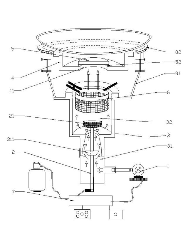
[0032] Such as figure 1 , Figure 4 , Figure 7 , Figure 8As shown, the present invention includes a fan 1, a gas channel 2, a furnace chamber 3, a furnace core 6, a furnace 4 and a support device for supporting a pot, and the pot is supported above the furnace 4 by the support device, and A gap is formed with the furnace hearth 4, and the support device can adopt a variety of different support methods. In the furnace chamber 3, from bottom to top, there are respectively an intake area 31, a mixing area 32, and a combustion area 33 that are sequentially connected. The fan 1 is in gas communication with the air intake area 31, the gas channel 2 extends from the outside of the furnace chamber 3 through the air intake area 31 into the mixing area 32, and the bottom of the furnace 4 is provided with a combustion chamber. The through hole 41 communicates with the combustion zone 33, and the furnace core 6 is arranged in the combustion zone 33. The present invention also include...

Embodiment 2

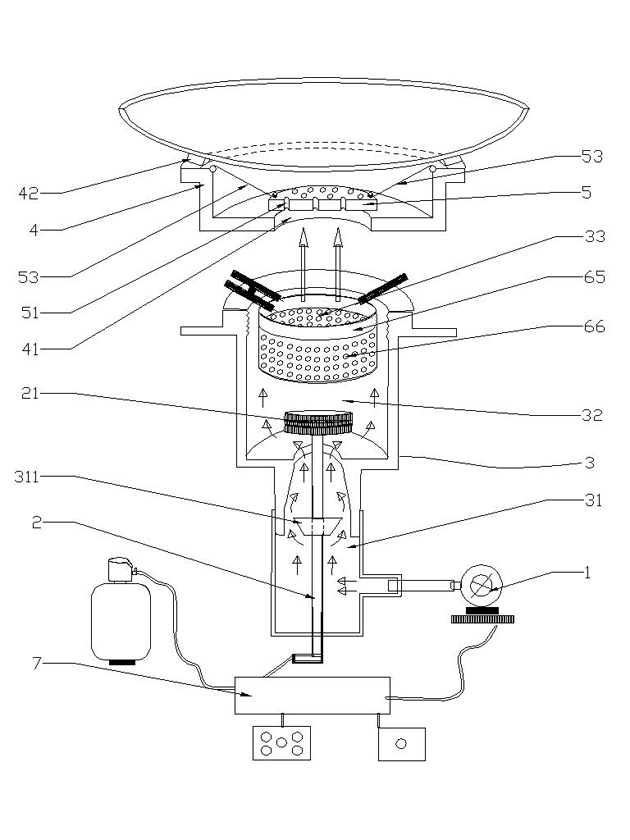
[0037] Such as figure 2 , Figure 5 As shown, in the present embodiment, the cover plate 5 is provided with a plurality of through holes 51, and the flame of the first combustion chamber can directly enter the first combustion chamber through the through holes 51 of the cover plate 5 to oppose the pot. tool for heating. The diameter of the through hole 51 is 4mm˜40mm.

[0038] In this embodiment, the support device is a fixed stay rope 53, one end of the fixed stay rope 53 is fixedly connected to the cover plate 5, and the other end is connected to the upper part of the furnace 4, and the fixed stay rope 53 is used to connect the The cover plate 5 is suspended in the air, and the fixed stay rope 53 is made of high temperature resistant material.

[0039] The solution of the furnace core 6 in this embodiment adopts a tubular object with an open upper end, which includes a furnace core tube 65 , and a plurality of furnace core holes 66 are opened on the side wall and bottom ...

Embodiment 3

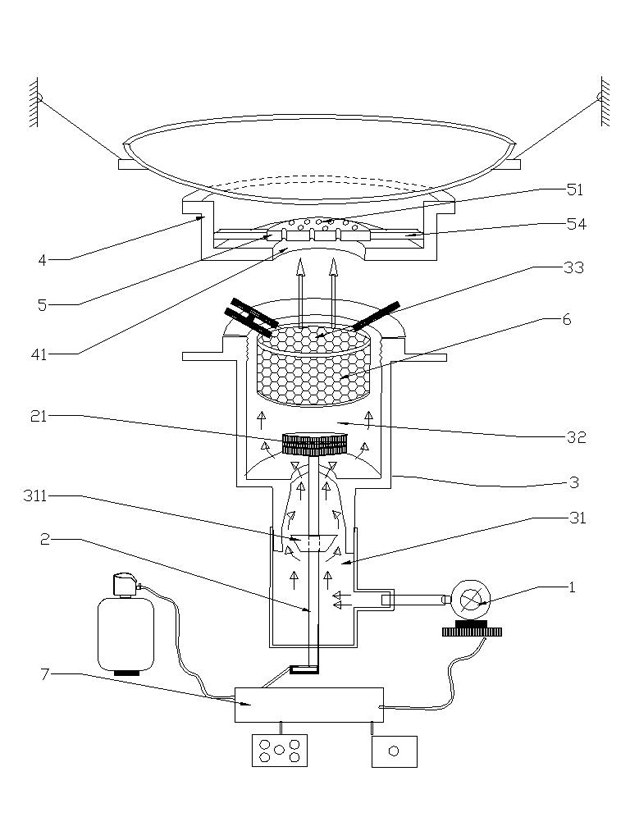
[0049] Such as image 3 , Image 6 As shown, in this embodiment, the bracket device is a fixed cross bar 54, one end of the fixed cross bar 54 is connected to the cover plate 5, and the other end is connected to the inner side wall of the furnace 4, and the cross bar 54 is used to 54 to fix the cover plate 5 on the top of the combustion through hole 41, and the fixed cross bar 54 is made of high temperature resistant material. When in use, the fixed cross bar 54 can be heated with the cover plate 5 and The furnace 4 generates high-temperature infrared heat radiation together. The material of the cover plate 5 and the furnace 4 in this embodiment is alumina ceramics, and the material of the fixed cross bar 54 is nickel-chromium alloy.

[0050] In this embodiment, the gap between the cover plate 5 and the bottom of the furnace 4 is 40mm, and the gap between the pot and the furnace is 40mm at the narrowest point.

[0051] The technical solution adopted by the furnace core 6 in ...


PUM


Abstract

The invention discloses an energy-saving furnace with a secondary combustion structure, which aims to provide an energy-saving furnace having the advantages of combustion stability and sufficiency, cleaning and heating evenness, and high heating efficiency. The energy-saving furnace comprises a draught fan (1), a gas channel (2), a furnace chamber (3), a furnace core (6), a furnace hearth (4), a cover plate (5) and a supporting device used for supporting cookware, wherein an air intake area (31), a mixing area (32) and a combustion area (33) are respectively arranged in the furnace chamber (3) from bottom to top; the draught fan (1) is communicated with the air intake area (31); the gas channel (2) extends into the mixing area (32); the bottom of the furnace hearth (4) is provided with acombustion through hole (41); the furnace core (6) is arranged in the combustion area (33); the cover plate (5) is arranged above the combustion through hole (41); a gap is formed between the cover plate (5) and the bottom of the furnace hearth (4) through a support device; the cover plate (5) and the furnace core (6) form a first combustion chamber; and the cover plate (5), the furnace hearth (4) and cookware matched with the furnace hearth (4) form a secondary combustion chamber. The invention can be widely applied to the field of furnaces.

Description

technical field [0001] The invention relates to an energy-saving furnace with a secondary combustion structure. Background technique [0002] Gas stoves are widely used in many places. Compared with conventional gas stoves, the application number provided by the applicant is 201010241872.9, and the name is the boiler chamber combined exhaust device and energy-saving stove. A relatively airtight, flat and narrow combustion heat conduction space, because the space is relatively airtight, the heat energy is lost less, the temperature is higher, and the mixture of gas and air with a reasonable ratio is easy to ignite and burn more fully, and also promotes the The temperature in the space can be raised rapidly, so as to achieve the technical purpose of good energy saving effect and less heat loss, and solve the technical problems of large energy loss and low gas utilization rate of conventional gas stoves; Gas installation and energy-saving stove technology is not perfect, there...

Claims


Application Information

Patent Timeline
Patent Type & Authority Applications(China)
IPC IPC(8): F24C3/00F24C3/08F24C3/12F24C15/10
CPCY02B40/166Y02B40/00
Inventor 曾文洲
Owner 曾文洲
Learn More