
Wavelength division multiplexing device for distributed optical fiber temperature sensor

A wavelength division multiplexing device and temperature sensor technology, applied in thermometers, optical components, thermometers with physical/chemical changes, etc., can solve problems such as insufficient isolation, system failure, and isolation that is difficult to exceed 40dB

Inactive Publication Date: 2011-05-18
KINGSHORE NEW RESOURCES ELECTRIC JIANGSU
View PDF4 Cites 4 Cited by
  • Summary
  • Abstract
  • Description
  • Claims
  • Application Information

AI Technical Summary

Problems solved by technology

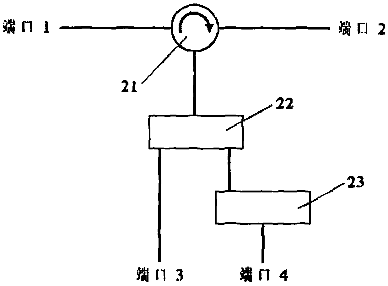
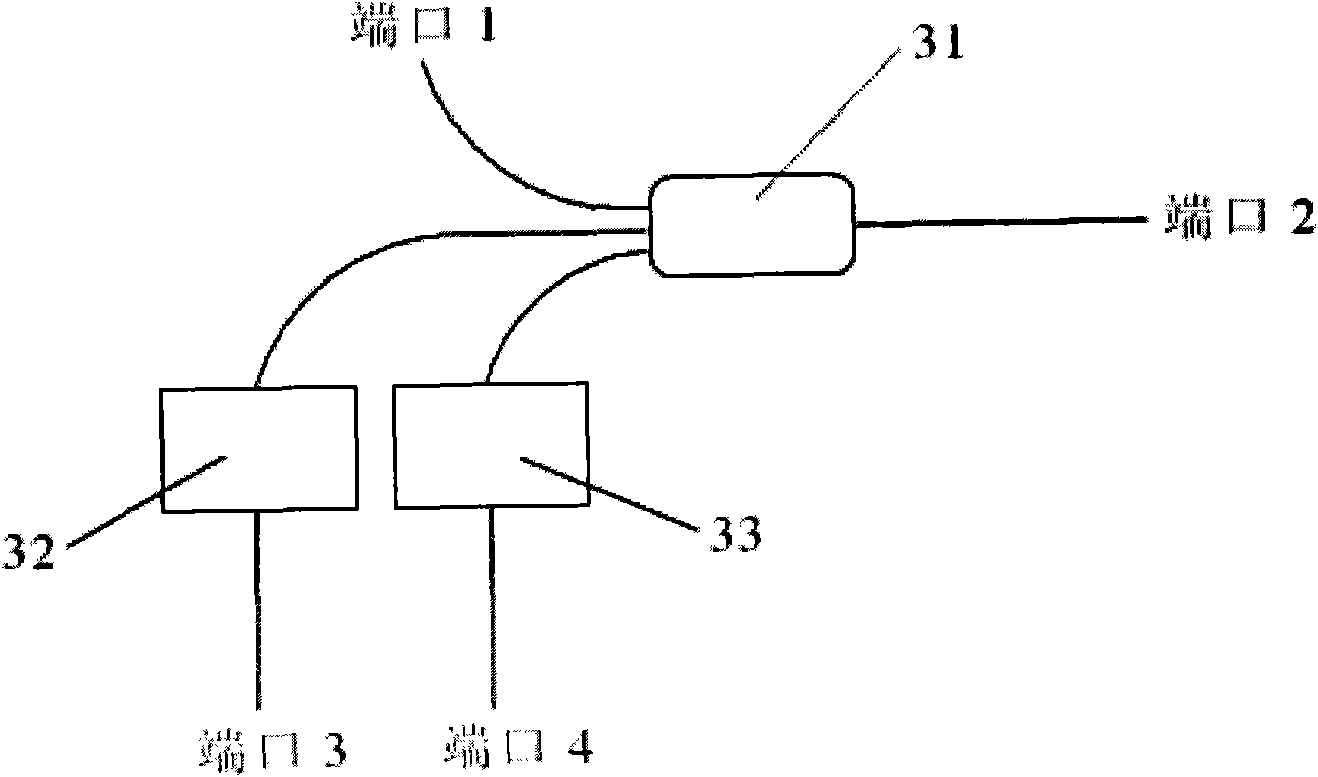
First of all, this wavelength division multiplexing device uses a 1X3 bidirectional coupler, which will introduce an additional loss of about 9.5dB (10log(1 / 9)=9.5dB), which greatly weakens the available anti-Stokes light and Stokes light intensity; Secondly, the isolation of the device is difficult to exceed 40dB, unless a very special filter is designed, the reason is the same as above
[0007] If the above-mentioned conventional wavelength division multiplexing device is used in a distributed optical fiber temperature sensor, usually due to insufficient isolation, it will cause mutual crosstalk between anti-Stokes light and Stokes light, and interference of Rayleigh scattered light, In this case, it is difficult to obtain accurate temperature information and high resolution. In severe cases, the temperature curve may even be distorted, and the system cannot work normally.

Method used


Image

  • Wavelength division multiplexing device for distributed optical fiber temperature sensor
  • Wavelength division multiplexing device for distributed optical fiber temperature sensor
  • Wavelength division multiplexing device for distributed optical fiber temperature sensor

Examples


Embodiment Construction

[0018] The technical scheme of the present invention will be described in detail below in conjunction with the drawings:

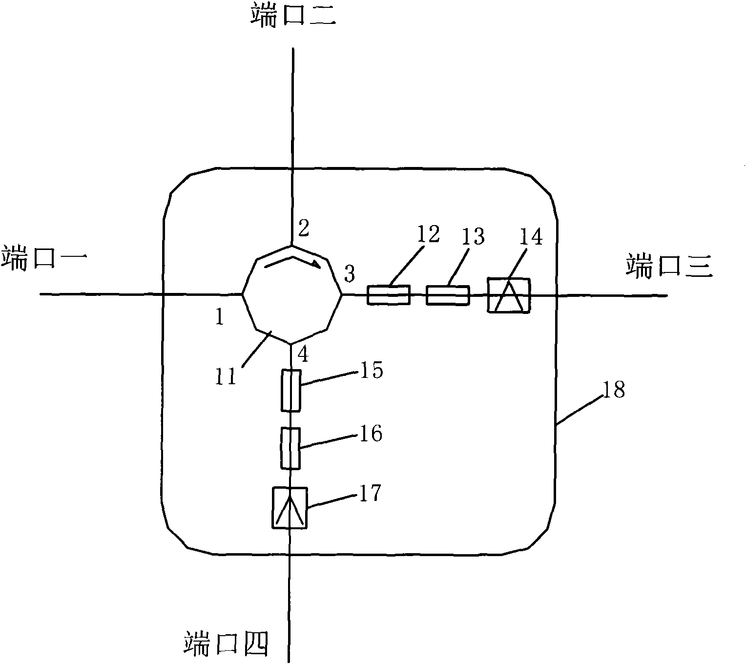
[0019] Such as figure 1 with 4 , Is a wavelength division multiplexing device for distributed optical fiber temperature sensors, which mainly includes a housing 18, which is such as Figure 4 Shown is a thermal insulation shell with a thermal insulation layer, the shell is a double-layer double-layer plastic, including an outer shell 41 and an inner shell 42, with an air insulation layer 43 in the middle, and four FCs are arranged on the shell 18 / APC connector fiber jumper, as four ports, respectively represented as port one, port two, port three and port four; the housing is provided with an optical circulator 11 with four ports, the first port 1 of the optical circulator 11 , The second port 2 is directly connected to port 1 and port 2 on the housing, respectively. A fiber grating 12 with Rayleigh scattering wavelength is connected in series between the t...


PUM

PropertyMeasurementUnit
isolationaaaaaaaaaa
widthaaaaaaaaaa
wavelengthaaaaaaaaaa

Abstract

The invention discloses a wavelength division multiplexing device for a distributed optical fiber temperature sensor in the field of optical fiber sensors. The device comprises four ports formed on a shell; an optical circulator with four ports is arranged in the shell; first and second ports of the optical circulator are directly connected to a port 1 and a port 2 on the shell respectively; a fiber Bragg grating with Rayleigh scattering wavelength, a fiber Bragg grating with Stokes wavelength and a band-pass filter with anti-Stokes wavelength are connected in series between a third port of the optical circulator and a port 3 on the shell; the fiber Bragg grating with the Rayleigh scattering wavelength, a fiber Bragg grating with the anti-Stokes wavelength and a band-pass filter with the Stokes wavelength are connected in series between a fourth port of the optical circulator and a port 4 on the shell; and a light path in the optical circulator circulates from the first port to the fourth port step by step. The device can reliably separate anti-Stokes light from Stokes light, the accurate temperature information can be acquired further, and the temperature resolution of the system is improved.

Description

Technical field [0001] The invention relates to a wavelength division multiplexing device, in particular to a wavelength division multiplexing device for a distributed optical fiber temperature sensor, and belongs to the technical field of optical fiber sensors. Background technique [0002] Since JPDakin et al. successfully realized the distributed temperature measurement technology based on Raman scattering for the first time in 1985, people have carried out extensive research on various technologies for realizing distributed optical fiber temperature sensing. Sensing technology has the most extensive practical application. Compared with traditional sensors, distributed optical fiber temperature sensors have many outstanding advantages: the optical fiber itself is used as the sensing medium, and thousands of points of temperature information distributed along the optical fiber can be obtained in one measurement, which realizes continuous distributed measurement and reduces Mea...

Claims


Application Information

Patent Timeline
Patent Type & Authority Applications(China)
IPC IPC(8): G01K11/32G02B6/293G02B5/18G01K11/3206G01K11/322
Inventor 周金龙朱冬宏田群
Owner KINGSHORE NEW RESOURCES ELECTRIC JIANGSU
Learn More