

Airborne vision enhancement method and device
A technology of visual enhancement and processing, which is applied in the field of visual enhancement, can solve problems such as lack of comprehensive consideration, and achieve the effects of improving perception, good visual effect, and convenient design
- Summary
- Abstract
- Description
- Claims
- Application Information
AI Technical Summary
Problems solved by technology
Method used
Image

Examples
Embodiment Construction
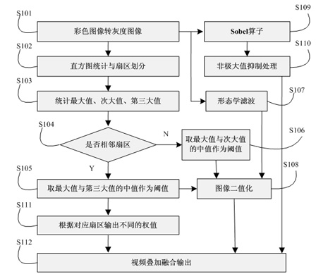
[0052] In order to make the technical means, creative features, goals and effects achieved by the present invention easy to understand, the present invention will be further described below in conjunction with specific illustrations.
[0053] see figure 1 , the airborne scene enhancement method in this embodiment includes the following steps:
[0054] S101. Perform grayscale transformation on an input digital image.
[0055] In this step, the formula used to convert the color image to a grayscale image is:
[0056] Gray = 0.3R + 0.59G + 0.11B,
[0057] Among them, Gray is the gray value of the converted image, and R, G, and B are the red, green, and blue components of the original color image, respectively.
[0058]Since the human eye has the highest sensitivity to green, the second to red, and the lowest to blue, the most reasonable grayscale image can be obtained by using this formula.
[0059] S102. Perform histogram statistics and sector division.
[0060] Divide the ...
PUM
 Abstract
Description
Claims
Application Information