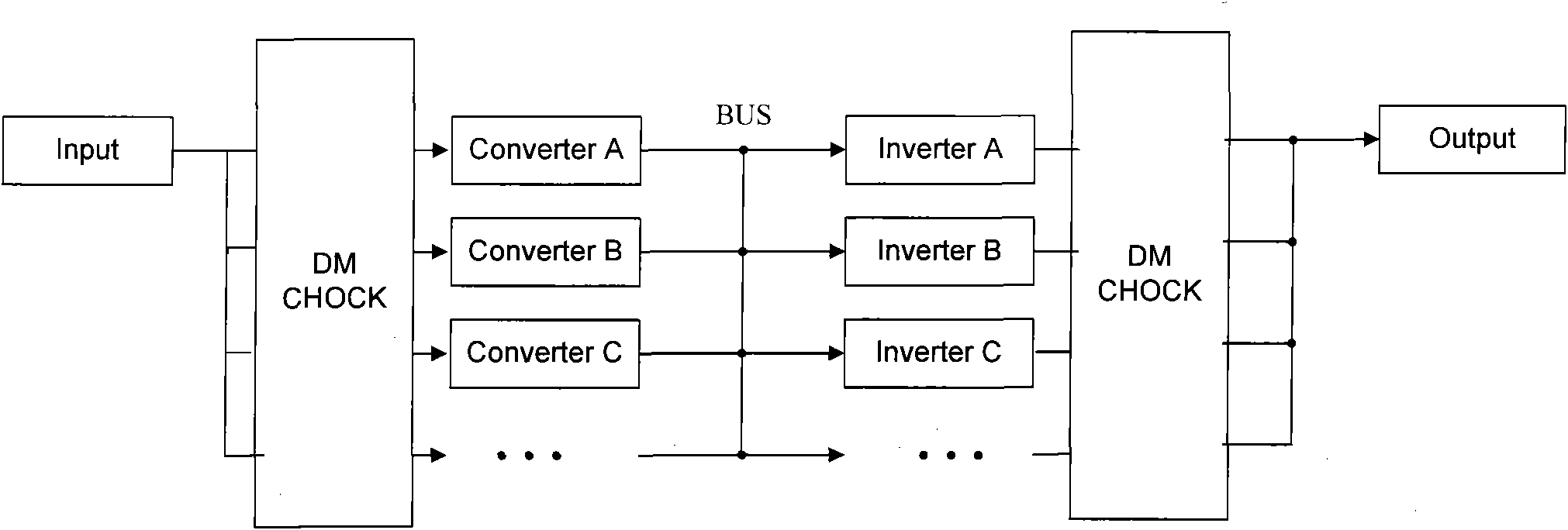
Circuit capable of realizing PFC (Power Factor Correction) flow-equalization parallel connection and control method thereof
A circuit and parallel technology, applied in sustainable manufacturing/processing, conversion equipment with intermediate conversion to AC, climate sustainability, etc., can solve the problems of low current flow, slow response, long adjustment time, etc. The control circuit is simple, the response speed is fast, and the effect is easy to achieve
- Summary
- Abstract
- Description
- Claims
- Application Information
AI Technical Summary
Problems solved by technology
Method used
Image
Examples
Embodiment 1
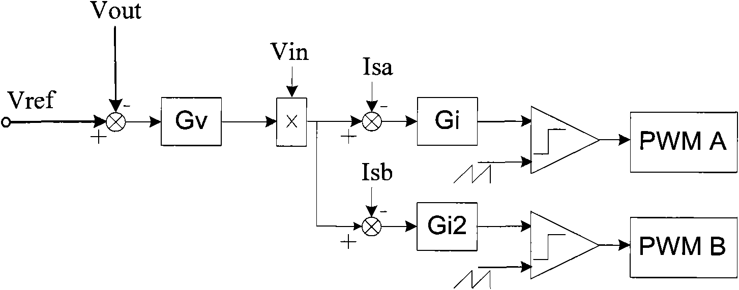
[0036] The hardware circuit and control method of the present invention will be analyzed below in combination with the PFC circuit of the double-boost architecture. Since the structure is symmetrical in the positive and negative half cycles of the mains, only the circuit on the positive side is used as an example for illustration. Such as Figure 4 As shown, thyristor SCR1, inductor L1, switch Q1, freewheeling diode D1 and capacitor C form the positive side of a double-boost PFC circuit; thyristor SCR2, inductor L2, switch Q2, freewheeling diode D2 and capacitor C The positive side of the PFC circuit that forms another double-boost architecture, their inputs are connected in parallel, and their outputs are also connected in parallel. The sampling circuit samples the input mains voltage, the voltage of the output capacitor C and the currents of the inductors L1 and L2 respectively. The control part chooses DSP (Digital Signal Processor) to realize, so the hardware circuit is ...
Embodiment 2
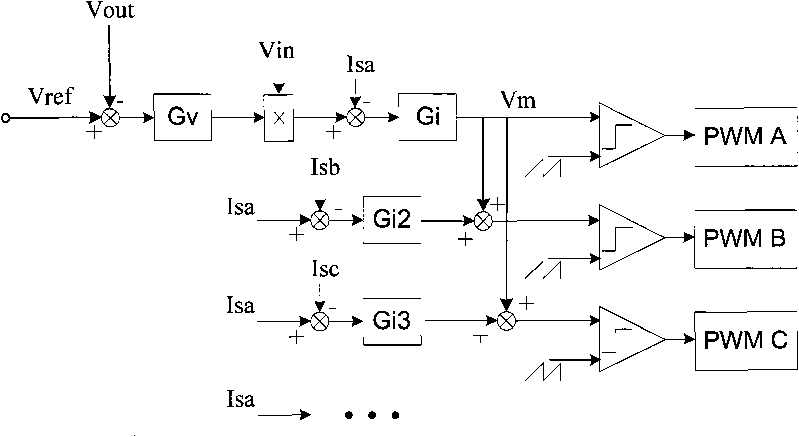
[0041] Such as Figure 5 As shown, a plurality of PFC circuits are connected in parallel, and the hardware circuit of the power part is the same as in Embodiment 1, the input is connected in parallel, and the output is also connected in parallel. The hardware circuit part is omitted in the figure. The voltage loop of the main controller is 501, which is the same as the first embodiment of the present invention; the current loop is 502, and its current feedback is mainly the PFC inductor current, not the average current; the number of current error control loops corresponds to the parallel PFC circuit, as shown in Fig. Shown 503 is the current error control loop corresponding to the PFC-A circuit, and its current is given as ΣIs / X, where X is the number of parallel PFC boards. Gi1, Gi2, and Gi3 are respectively the controllers of the current error loops of the PFC-A circuit, the PFC-B circuit and the PFC-C circuit, corresponding to 504 in the figure. Each error control loop i...
Embodiment 3
[0043] Such as Image 6 As shown, it is Embodiment 3 of the present invention, the PFC circuits connected in parallel are of different power levels. The rectifier bridge Bridge, inductor L1, switch tube Q1, diode D1 and capacitor C form PFC circuit 1; the rectifier bridge Bridge, inductor L2, switch tube Q2, diode D2 and capacitor C form PFC circuit 2. The hardware parameters of the two PFC circuits are different, and the power is also different. The rated power of the first circuit is P1, and the rated current is I1; the rated power of the second circuit is P2, and the rated current is I2. Let circuit one be the main board, and circuit two be the sub-board. After the current sampling, the primary and secondary PFC current inductor current sampling signals iL1 and iL2 are obtained. After the circuit 2 samples the inductor L2 current, it processes the current sampling signal through a proportional link. The proportional link gain K=P1 / P2. Then, the average current feedback s...
PUM
 Abstract
Description
Claims
Application Information
 - R&D
- Intellectual Property
- Life Sciences
- Materials
- Tech Scout
- Unparalleled Data Quality
- Higher Quality Content
- 60% Fewer Hallucinations
Browse by: Latest US Patents, China's latest patents, Technical Efficacy Thesaurus, Application Domain, Technology Topic, Popular Technical Reports.
© 2025 PatSnap. All rights reserved.Legal|Privacy policy|Modern Slavery Act Transparency Statement|Sitemap|About US| Contact US: help@patsnap.com


