Power electronic transformer based on simple PFC (Power Factor Correction)

A technology of power electronics and transformers, which is applied in the field of power electronic transformers based on simple PFC, can solve the problems that affect the promotion and application of power electronic transformers, large switching losses, and high costs, so as to improve the overall conversion efficiency, reduce switching losses, and reduce the number of transformers. Effect

Inactive Publication Date: 2011-05-18
SOUTHEAST UNIV +1
View PDF6 Cites 21 Cited by
  • Summary
  • Abstract
  • Description
  • Claims
  • Application Information

AI Technical Summary

Problems solved by technology

[0004] At present, there are too many switching devices in the patents of power electronic transformers at home and abroad, the cost is high, the switching loss is large, and the conversion efficiency is not high, which affects the promotion and application of power electronic transformers to a certain extent.

Method used


Image

  • Power electronic transformer based on simple PFC (Power Factor Correction)
  • Power electronic transformer based on simple PFC (Power Factor Correction)
  • Power electronic transformer based on simple PFC (Power Factor Correction)

Examples


Embodiment Construction

[0022] The present invention will be further described below in conjunction with the accompanying drawings and embodiments.

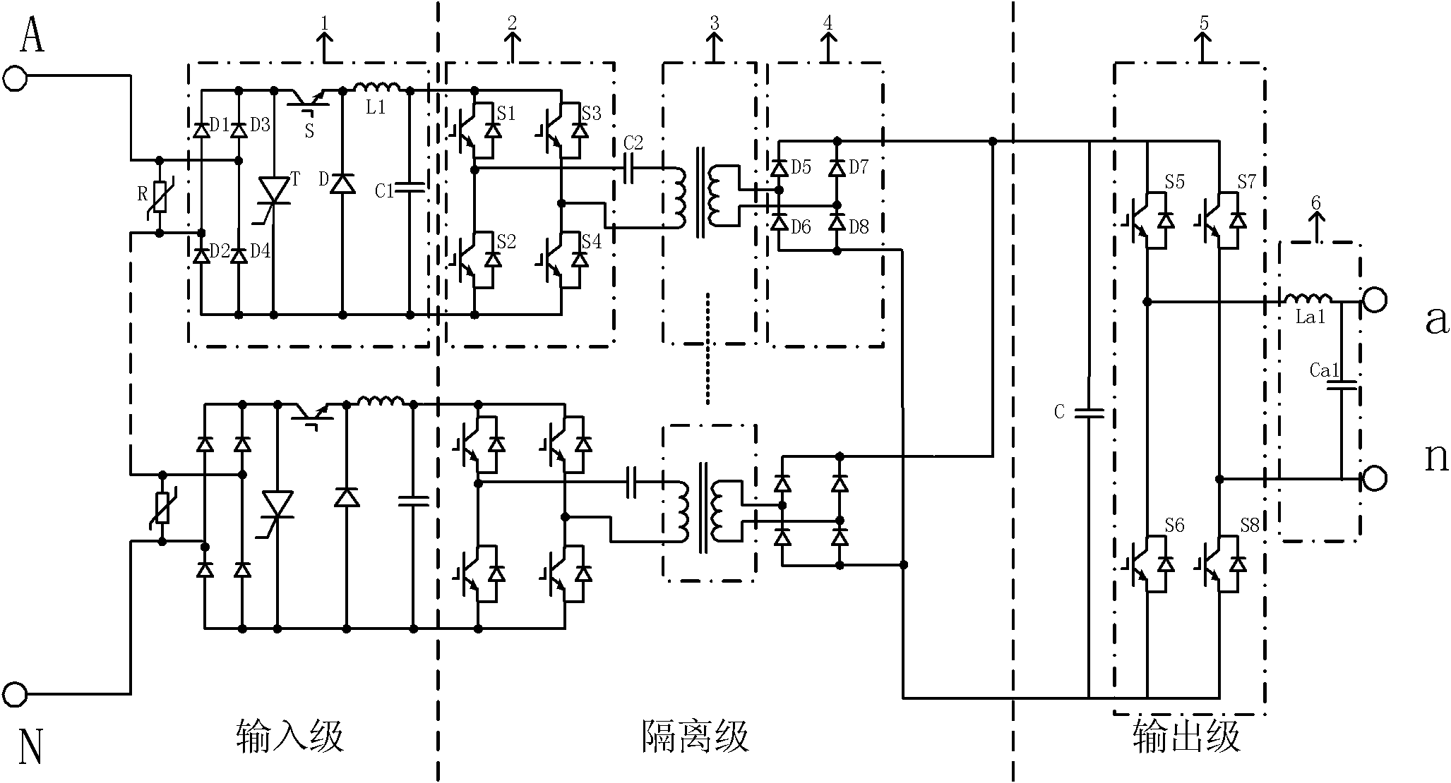
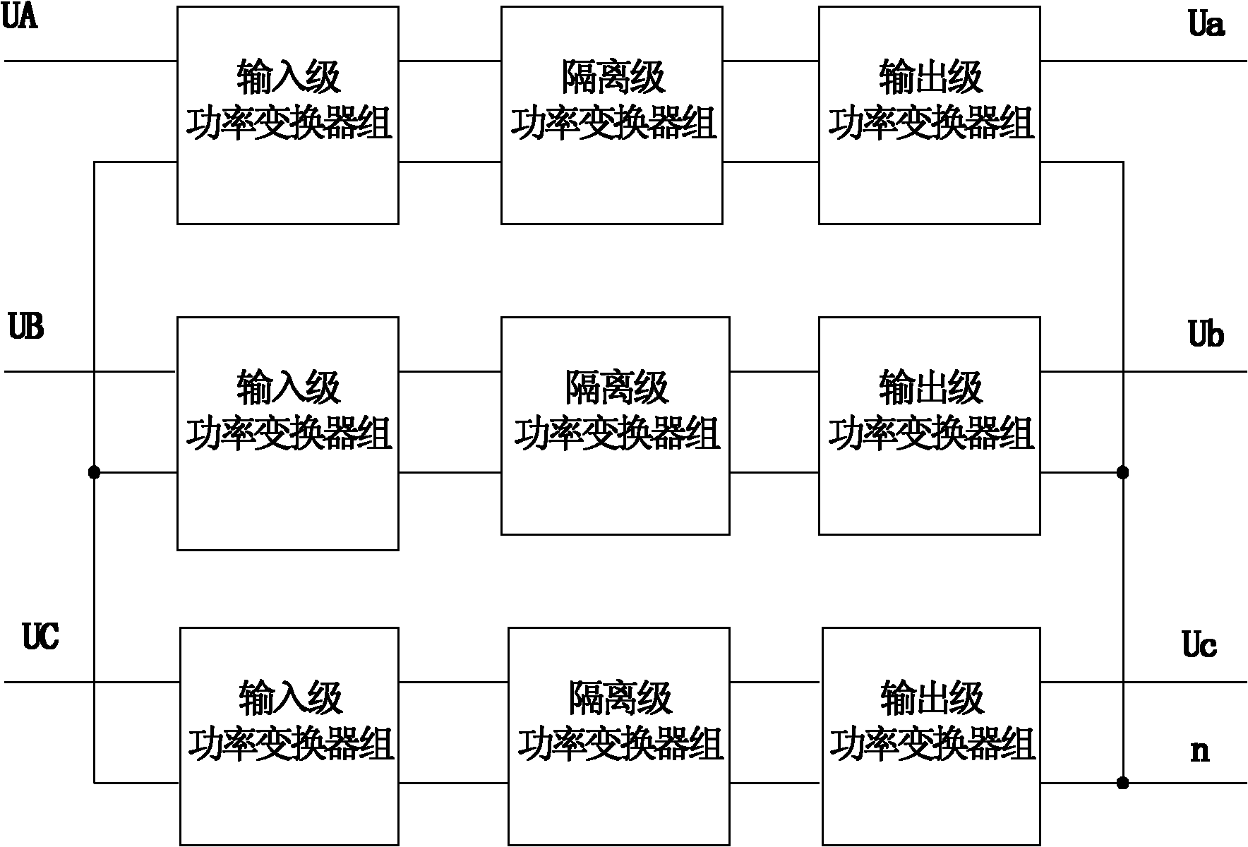
[0023] Such as figure 2 As shown, a simple PFC-based power electronic transformer of the present invention has the same and independent single-phase structure in its three-phase circuit, and each phase includes an input stage, an isolation stage and an output stage, and the input stage, isolation stage and output stage Each includes a power converter group; the input terminals of the power converter group of each single-phase input stage and the power converter group of the output stage are respectively connected in star form. The isolation stage includes a high-frequency DC / AC link, a high-frequency transformer, and a high-frequency AC / DC link; the single-phase structure includes a varistor R connected in parallel to the input end of the basic power unit, wherein the output end of the first power converter 1 is connected to The input terminal of the ...


PUM


Abstract

The invention discloses a power electronic transformer based on simple PFC (Power Factor Correction). All single phase structures in a three-phase circuit are same and independent to each other, wherein each phase comprises an input grade, an isolation grade and an output grade; input ends of an input-grade power transformer group and an output-grade power transformer group of each single phase are connected in a star shape; the input grade of each single phase adopts a series connection way; the input-grade power transformer group comprises a diode bridge-type circuit and a buck circuit and can realize the control of a power factor, and the alternating side of each power transformer group is connected in parallel with a pressure sensitive resistor; the isolation grade comprises a high-frequency DC / AC, a high-frequency transformer and a high-frequency AC / DC link, wherein a primary edge of the high-frequency transformer is connected in series with a capacitor, and the loss consumption of a switch tube is reduced under the action of a resonance soft switch; an output side of the isolation grade adopts a parallel connection way; and the output-grade power transformer group adopts a bridge-type inverting circuit, and an output side of the output-grade power transformer group is also connected with a filter. The invention has the advantages of simplifying the circuit structure, reducing the cost, realizing the power factor correction and resonance soft switch and increasing the conversion efficiency.

Description

technical field [0001] The invention relates to a power electronic transformer applied in a power distribution network, in particular to a simple PFC-based power electronic transformer. Background technique [0002] Traditional power transformers usually adopt iron core oil-immersed type, which has the advantages of simple manufacturing process and high reliability, but the disadvantages are also very obvious, such as large volume and weight, high no-load loss, insulating oil is a threat to the environment, and the function is relatively simple , when overloaded, it is easy to cause the output voltage to drop and generate harmonics. When it is put into the power grid, it will also cause a large excitation inrush current, causing pollution to the power grid. The shortcomings and single functions of traditional power transformers are difficult to meet the needs and goals of future power grid construction. As a new type of energy conversion equipment, power transformers have t...

Claims


Application Information

Patent Timeline
Patent Type & Authority Applications(China)
IPC IPC(8): H02M5/44H02M5/458H02M1/42
CPCY02B70/1491Y02B70/126Y02B70/10Y02P80/10
Inventor 赵剑锋季振东翟广平蒋本洲冯祖康于鹏王辉苏晓龙
Owner SOUTHEAST UNIV
Why Eureka
Try Eureka