Refrigeration cycle device and control method therefor

A technology of circulation device and control valve, which can be used in fluid circulation arrangement, heating and ventilation control system, irreversible circulation compressor, etc. big effect

Active Publication Date: 2011-05-18
MITSUBISHI ELECTRIC CORP
View PDF1 Cites 39 Cited by
  • Summary
  • Abstract
  • Description
  • Claims
  • Application Information

AI Technical Summary

Problems solved by technology

[0003]On the other hand, because the conventional refrigeration cycle devices use non-flammable HFC (hydrofluorocarbon) refrigerants such as R410A, the refrigerant has a large greenhouse effect and is produced by carbon dioxide. About 2000 times, when the refrigeration cycle is discarded or repaired, if the refrigerant accidentally leaks, it will not decompose for a long time and float in the atmosphere, so it will accelerate global warming

Method used


Image

  • Refrigeration cycle device and control method therefor
  • Refrigeration cycle device and control method therefor
  • Refrigeration cycle device and control method therefor

Examples


Embodiment approach 1

[0033] (refrigeration cycle)

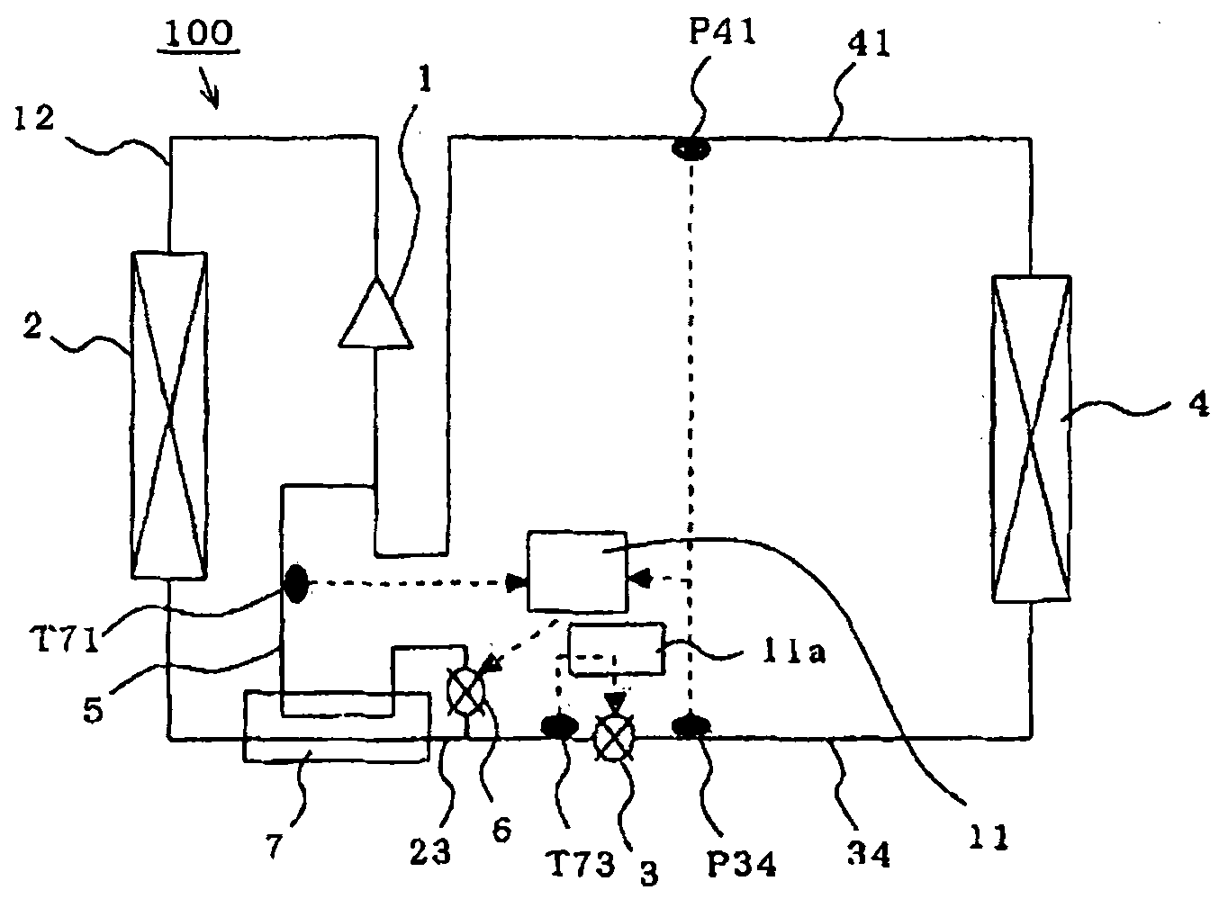
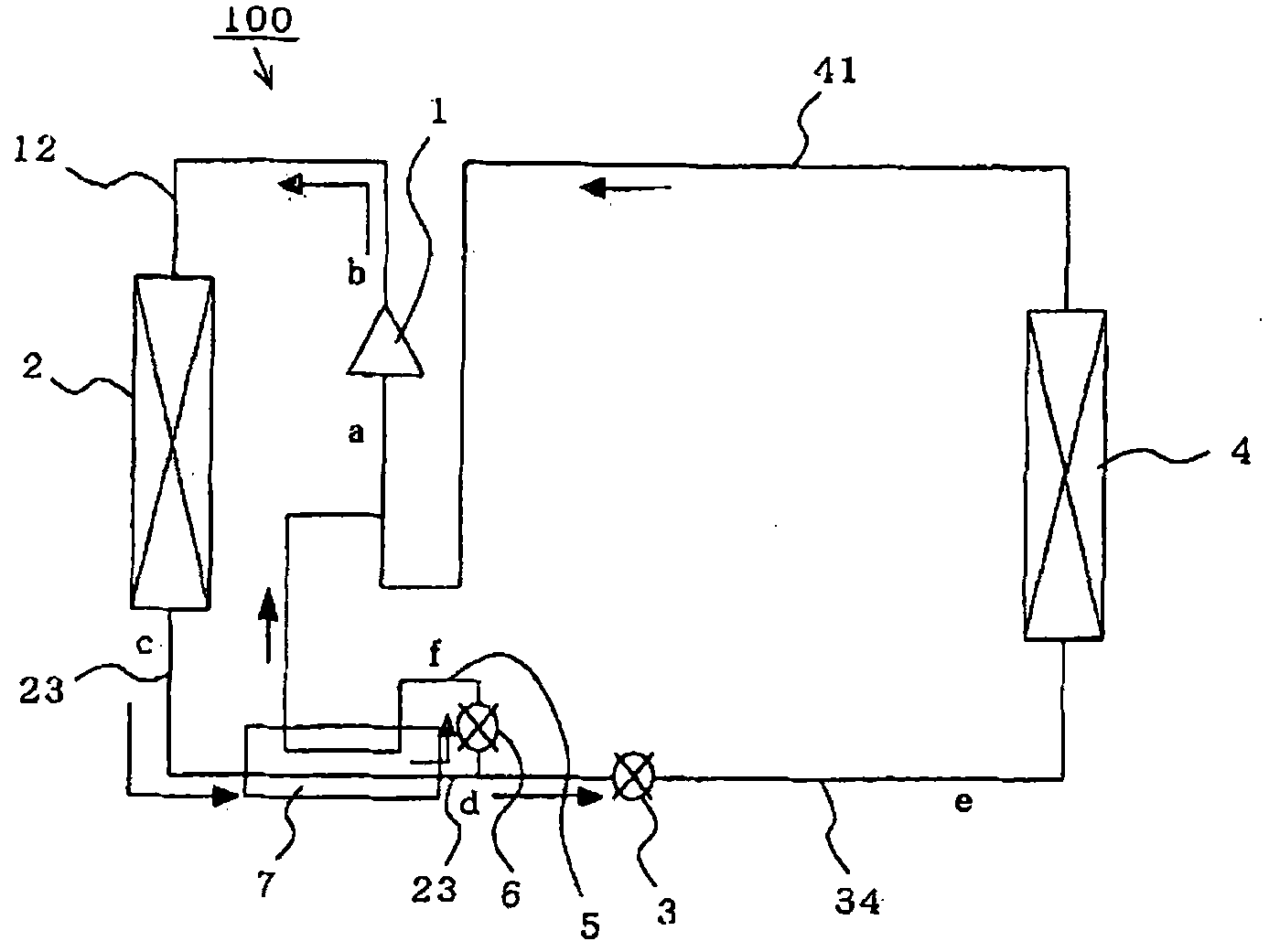
[0034] figure 1 It is a refrigerant circuit diagram explaining the structure of the refrigeration cycle apparatus concerning Embodiment 1 of this invention. exist figure 1Among them, the refrigeration cycle apparatus 100 has a main circuit including a compressor 1 for compressing refrigerant, a condenser 2 for condensing the compressed refrigerant, and an expansion valve (such as an electronic expansion valve) for expanding the condensed refrigerant. flow control valve, capillary tube, etc.) 3, evaporator 4 for evaporating the expanded refrigerant, high temperature and high pressure piping 12 connecting compressor 1 and condenser 2, medium temperature and high pressure piping 23 connecting condenser 2 and expansion valve 3, connecting The low-temperature and low-pressure piping 34 connecting the expansion valve 3 and the evaporator 4 , and the medium-temperature and low-pressure piping 41 connecting the evaporator 4 and the compressor 1 .

[0...

Embodiment approach 2

[0048] (Embodiment 2: Control Method)

[0049] Below, refer to figure 2 Control of the expansion valve 3 and the bypass expansion valve 6 by the control mechanism of the refrigeration cycle apparatus shown in Embodiment 1 will be described.

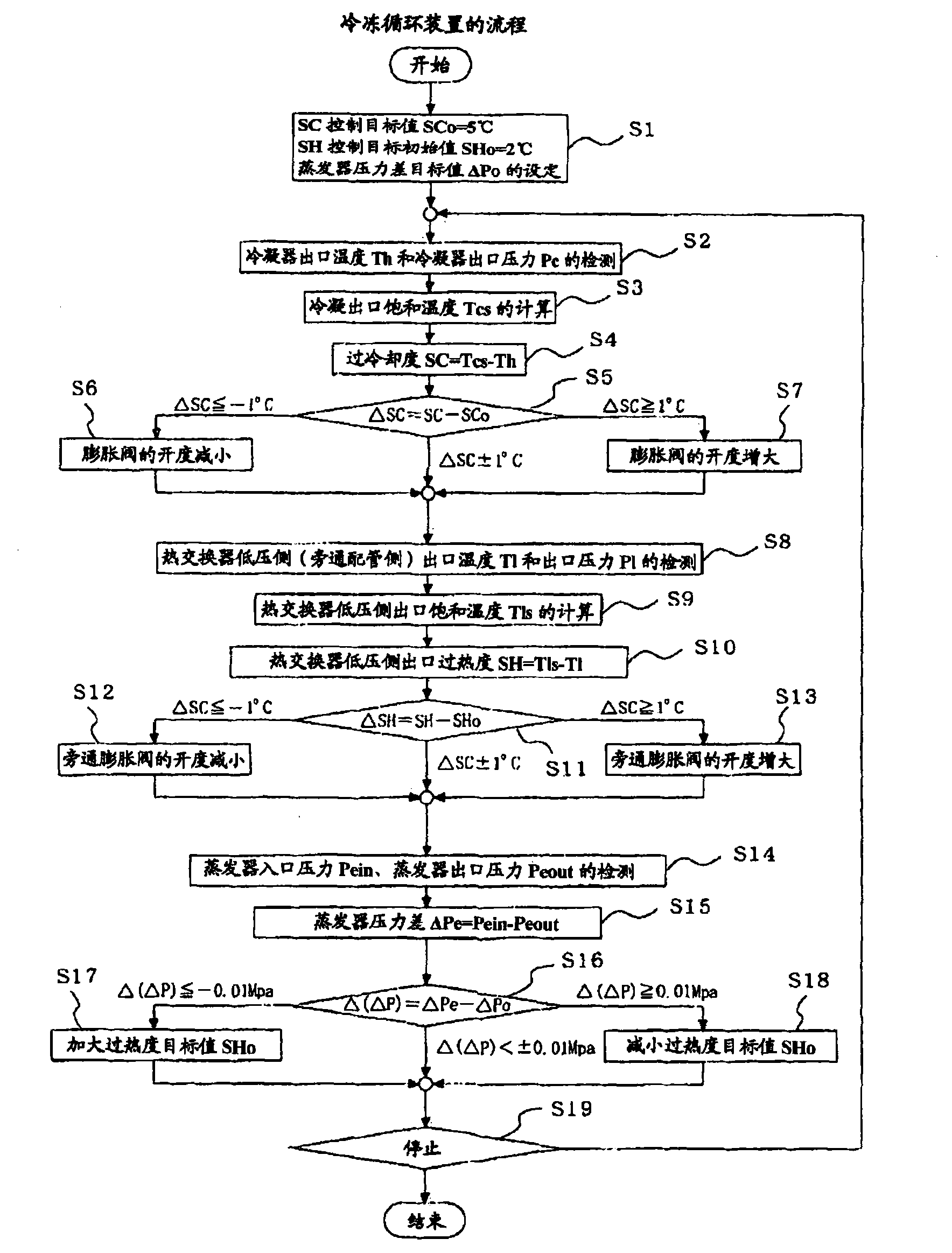
[0050] figure 2 It is a flowchart showing the degree of supercooling control and the degree of superheating control of the control means for explaining the control method of the refrigeration cycle apparatus according to Embodiment 2 of the present invention.

[0051] exist figure 2 First, the subcooling degree control unit 11a and the superheating degree control unit 11b respectively set initial values ​​for the supercooling degree target value SCo and the superheating degree target value SHo (for example, SCo=5°C, SHo=2°C) (S1) . This initial value is a value (a positive value equal to or greater than 0) that is appropriately adjusted according to the installation conditions and the type of refrigeration device, and is stored in ...

Embodiment approach 3

[0102] (refrigeration cycle)

[0103] Figure 5 It is a refrigerant circuit diagram explaining the structure of the refrigeration cycle apparatus concerning Embodiment 3 of this invention. exist Figure 5 In the refrigerating cycle device 200, the gas-liquid separator 8 is added to the low-temperature and low-pressure piping 34 in the refrigerating cycle device 100 (Embodiment 1), and the gas (steam) separated in the gas-liquid separator 8 is provided. A pipe (hereinafter, referred to as "gas pipe") 10 that supplies the compressor 1 is provided.

[0104] A flow control valve (hereinafter referred to as "gas flow control valve") 9 is provided in the middle of the gas piping 10, and a gas flow control valve inlet pressure sensor P89 is installed on the upstream side of the gas flow control valve 9 respectively. The downstream side of the valve 9 is provided with a gas flow control valve outlet pressure sensor P91.

[0105] Except for the above structure, the rest is the same...


PUM


Abstract

A refrigeration cycle device (100) in which a flammable refrigerant circulates comprises a bypass pipeline (5) connected such that part of the refrigerant flowing through a circulation pipeline from a condenser (2) to a flow control valve (3) bypasses the flow control valve (3) and an evaporator (4), a bypass flow control valve (6) for controlling the flow rate of the refrigerant flowing through the bypass pipeline (5), a heat exchanger (7) for allowing the refrigerant flowing through the bypass pipe line (5) after flowing out from the bypass flow control valve (6) and the refrigerant flowingthrough the circulation pipeline after flowing out from the condenser (2) to exchange heat with each other, and a supercooling degree sensor (T73) for detecting the supercooling degree of the refrigerant at an inlet of the flow control valve (3). At least either the flow control valve (3) or the bypass flow control valve (6) is so controlled that the supercooling degree of the refrigerant at the inlet of the flow control valve (3) is equal to or more than a predetermined value.

Description

technical field [0001] The present invention relates to a refrigerating cycle device, and more particularly to a refrigerating cycle device using a refrigerant with a low global warming coefficient. Background technique [0002] Conventional refrigerating cycle devices use refrigerant piping to connect a compressor that compresses a medium-temperature and low-pressure refrigerant (hereinafter, referred to as "medium-temperature and low-pressure" for convenience of explanation) to a compressed refrigerant (hereinafter, referred to as "medium-temperature and low-pressure"). "High-temperature and high-pressure refrigerant") condenses condenser, expansion valve that expands condensed refrigerant (hereinafter, referred to as "medium-temperature and high-pressure refrigerant"), expands refrigerant (hereinafter, referred to as "low-temperature and low-pressure refrigerant") The evaporators for evaporating the agent") are connected in sequence (hereinafter, this structure is referre...

Claims


Application Information

Patent Timeline
Patent Type & Authority Applications(China)
IPC IPC(8): F25B1/00F24F11/02F25B49/02
CPCF25B2400/13F24F2011/0084F25B2600/2509F25B2500/19F25B2400/12F25B2700/21F25B41/00F24F11/36F25B40/02F25B40/06F25B2341/063F25B2341/064F25B2400/0419
Inventor 若本慎一亩崎史武仓持威饭岛等
Owner MITSUBISHI ELECTRIC CORP
Why Eureka
Try Eureka