Drip-imitating tube-type demister and demister device

A droplet-shaped, mist eliminator technology, applied in chemical instruments and methods, dispersed particle separation, separation methods, etc., can solve the problem of inability to effectively eliminate large mist droplets and uniformly distributed flue gas, tubular mist eliminator and mist eliminator The defogging efficiency and self-cleaning ability cannot meet the requirements, etc., to achieve the effect of increasing the area, reducing the flow resistance, and not easy to scale.

Active Publication Date: 2013-07-24
RPT SHANGHAI ENVIRONMENTAL EQUIP
View PDF1 Cites 0 Cited by
  • Summary
  • Abstract
  • Description
  • Claims
  • Application Information

AI Technical Summary

Problems solved by technology

[0003] The demisting efficiency and self-cleaning ability of the above-mentioned tubular demister and demister device cannot meet the requirements in some cases, and at the same time cannot effectively eliminate the effects of large fog droplets and evenly distributed smoke

Method used


Image

  • Drip-imitating tube-type demister and demister device
  • Drip-imitating tube-type demister and demister device
  • Drip-imitating tube-type demister and demister device

Examples


Embodiment 1

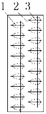
[0024] Such as figure 2 As shown, it is a structural schematic diagram of a two-layer tube-row imitation water-drop-shaped tube demister provided by the present invention, which includes two layers of parallel tube-rows 1, and the tube-row 1 is composed of evenly arranged cross-sections that are drop-shaped tubes 3 The two ends of the tube row 1 are respectively supported on the plate 2. The spacing between each tube row 1 is arbitrary.

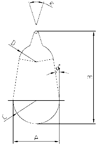
[0025] Such as figure 1 As shown, the major axis B of the drop-shaped cross-section of the water-drop-shaped pipe 3 is twice the minor axis A of the drop-shaped cross-section, and the large circle C of the drop-shaped cross-section is 1.3 times the small circle D of the drop-shaped cross-section. The head of the small circle D of the drop-shaped section has a taper of 35°, and the inclination a of the pipe 3 is 9°.

Embodiment 2

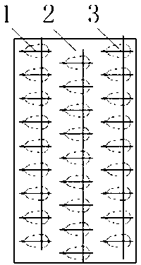
[0027] Such as image 3 As shown, it is a structural schematic diagram of a three-layer pipe row imitation water drop tube demister provided by the present invention. The difference between the imitation water drop tube demister of this embodiment and embodiment 1 is that There are three layers, and other structures are the same as in Embodiment 1.

Embodiment 3

[0029] Such as Figure 4A As shown, in order to use the demister device of the above-mentioned imitation water-drop-shaped pipe demister, the imitation water-drop-shaped pipe demister 5 is arranged at the upstream position of the flue gas desulfurization tower or the horizontal flue, and in the flue gas desulfurization tower or the horizontal flue A plate type mist eliminator 6 is arranged downstream of the channel.

[0030] Such as Figure 4B As shown, the flushing water pipes 10 of the water-drop-shaped tube demister 5 and the flat plate demister 6 are arranged upstream and downstream of the water-drop-shaped tube demister 5, while the downstream of the water-drop-shaped tube demister 5 It is necessary to arrange the flushing water pipe 10 to clean the blades of the flat plate mist eliminator 6 .

[0031] The water-drop-shaped tubular demister 5 is upstream at the inlet end of the flue gas, and downstream at the outlet end of the flue gas. The blades of the flat-plate mis...


PUM


Abstract

The invention provides a drip-imitating tube-type demister, which is characterized by comprising at least two layers of parallel rows of tubes, wherein the rows of tubes are formed by tubes which are uniformly arrayed, the two ends of the rows of tubes are respectively supported on a plate, and the direction of flue gas flow is vertical to the direction of the short axis of the inner tubes of therow of tubes. The invention also provides a demister device, which is characterized by comprising the drip-imitating tube-type demister, wherein the drip-imitating tube-type demister is arranged at aflue gas desulfurization tower or the upstream of a horizontal flue, the demister is arranged at the downstream of the flue gas desulfurization tower, or a vane demister is arranged at the downstreamof the horizontal flue. The invention has the advantages that the demister reduces partial flow resistance, the area for blocking mist drop can be enlarged, demisting effect is improved, and scale isnot easy to form.

Description

technical field [0001] The invention relates to an imitation drop-shaped tube for a tube-type mist eliminator, which is used for purifying flue gas in a flue gas desulfurization tower or a horizontal flue, and belongs to the technical field of flue gas purification devices. Background technique [0002] The Chinese Utility Model Patent No. ZL200920286171.X discloses a tube type demister and demister device. In the above-mentioned patent, the tube type demister includes at least two layers of parallel tube rows. The tube rows are composed of uniformly arranged tubes, and the two ends of the tube rows are respectively supported on the plates. axis are perpendicular to each other. The demister device includes the above-mentioned tube type demister, the tube type demister is arranged at the upstream position of the flue gas desulfurization tower or the horizontal flue, and the downstream position of the flue gas desulfurization tower is arranged with a flat plate demister, a s...

Claims


Application Information

Patent Timeline
Patent Type & Authority Patents(China)
IPC IPC(8): B01D45/06
Inventor 康明徐强隋鹏
Owner RPT SHANGHAI ENVIRONMENTAL EQUIP
Why Eureka
Try Eureka